
Electrically-ignited energy-saving cooking stove

An energy-saving stove and electric ignition technology, which is applied in the field of stoves, can solve problems such as unreasonable use of heat, inconvenient operation, and heat loss, and achieve the effects of improving energy waste, avoiding insufficient combustion, and improving inconvenience

Inactive Publication Date: 2016-10-12
蓝黎军
View PDF8 Cites 0 Cited by
  • Summary
  • Abstract
  • Description
  • Claims
  • Application Information

AI Technical Summary

Problems solved by technology

[0003] At present, the flames of traditional coal wood stoves are scattered and weak, and pass by the bottom of the pot, resulting in serious heat loss; the fuel inside the combustion zone cannot be in good contact with the air, resulting in incomplete combustion of the fuel; The directly discharged flue gas carries a large amount of heat and has not been rationally utilized, and the traditional ignition methods are lighters or matches, which also cause inconvenience to users
Therefore, ordinary stoves are inefficient to use, cause serious energy waste, and are inconvenient to operate
In order to advocate the energy saving and emission reduction advocated by the state, various developers and manufacturers develop and produce various stoves to the market, but they generally have the characteristics of complex structure and insufficient practicability.

Method used


Image

  • Electrically-ignited energy-saving cooking stove
  • Electrically-ignited energy-saving cooking stove
  • Electrically-ignited energy-saving cooking stove

Examples


Embodiment Construction

[0035] The present invention will be further described in detail below in conjunction with the accompanying drawings, so that those skilled in the art can implement it with reference to the description.

[0036] It should be understood that terms such as "having", "comprising" and "including" as used herein do not entail the presence or addition of one or more other elements or combinations thereof.

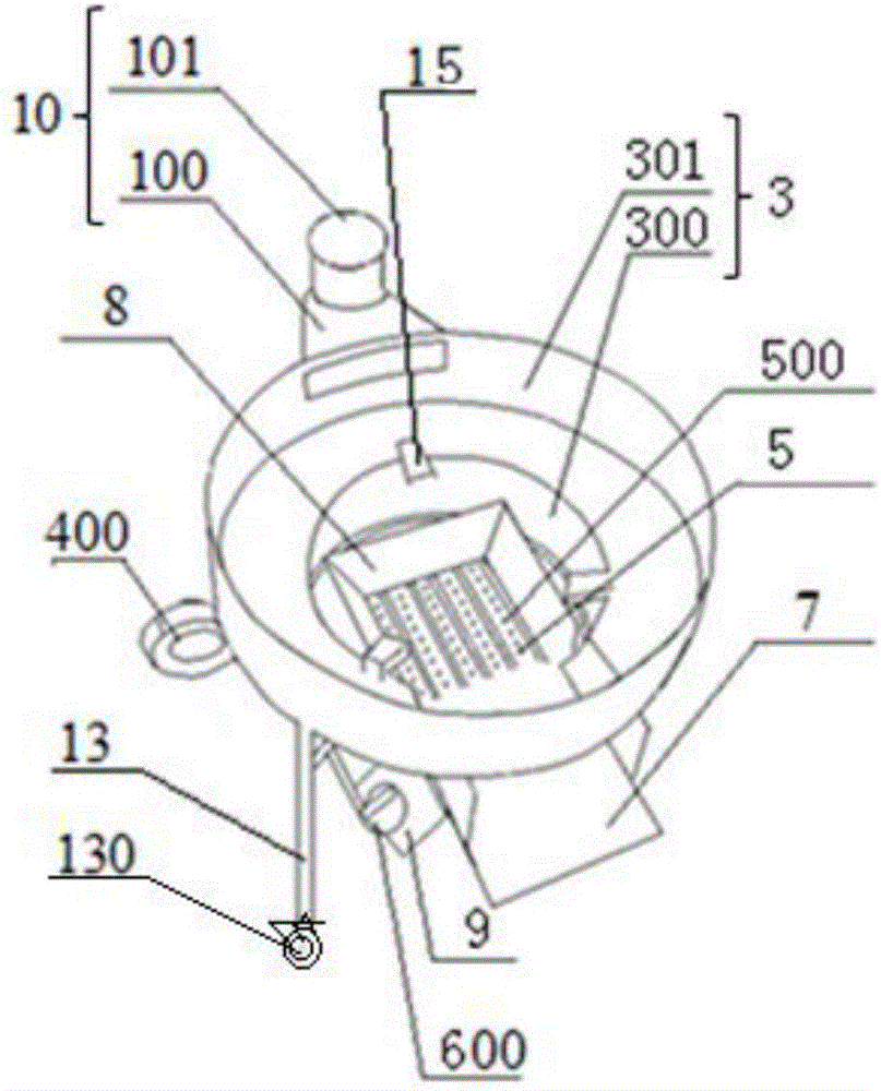
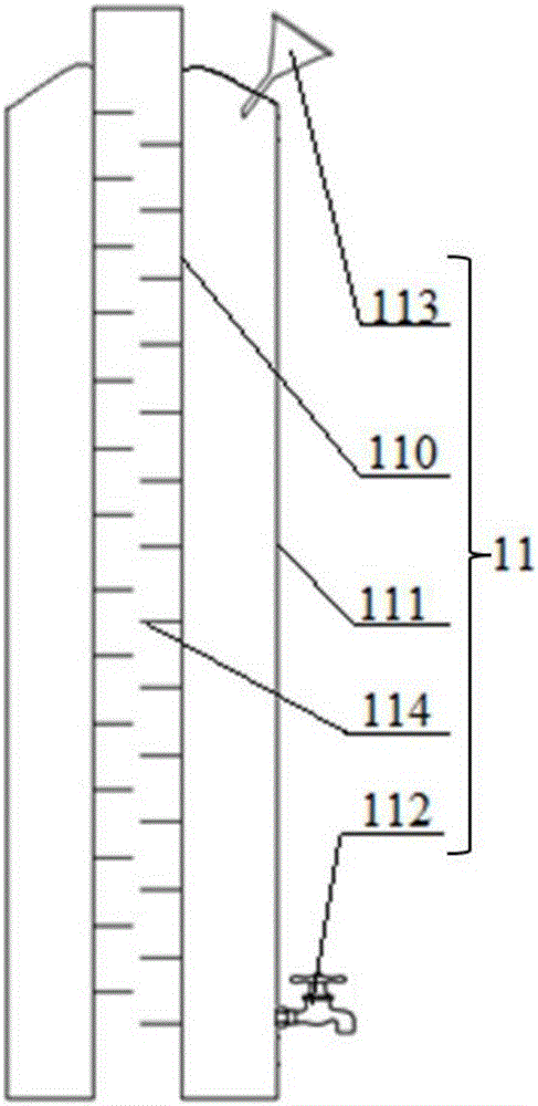
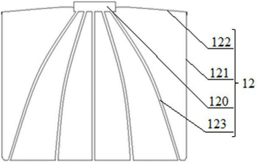
[0037] like Figure 1-6 As shown, the present invention provides an electric ignition energy-saving cooker, comprising:

[0038] Base 1, an ash box 2 is sleeved at the inner lower end of the base 1;

[0039] A stove 3, which includes a combustion cavity 300 fixed on the upper end of the base 1 and communicated with the base 1, and a support cavity 301 welded on the upper end of the combustion cavity 300 and communicated with the combustion cavity 300;

[0040] The air blast assembly 4 and a plurality of furnace bars 5, the air blast assembly 4 provides an air source for the fur...


PUM


Abstract

The invention discloses an electrically-ignited energy-saving cooking stove. The electrically-ignited energy-saving cooking stove comprises a base, an ash box, a combustion cavity, a supporting cavity, an air blowing assembly, a plurality of stove bars, an ignition assembly and a water tank. The air blowing assembly supplies an air source to the stove bars. Each stove bar is of a hollow tubular structure which is provided with multiple air outlets in the upper end at intervals, horizontally arranged at the communicating position of the combustion cavity and the base and close to one side of the base. A fence is obliquely arranged around the stove bars upwards. The side, close to a firewood inlet, of the fence communicates with the firewood inlet. The ignition assembly comprises a coal gas ignition switch, an ignition device, and a fire-jet head. The water tank comprises a first chimney inner pipe and a tank body. The first chimney inner pipe is provided with multiple baffles from bottom to top at equal intervals so that smoke can be discharged in an S-shaped manner. The electrically-ignited energy-saving cooking stove has the beneficial effects that fuel can sufficiently make contact with air, the phenomenon that a traditional coal firewood cooking stove is disordered and weak in flame is improved, the waste heat carried by the smoke is sufficiently used, energy waste is improved, movement is easy, and automatic ignition can be achieved.

Description

technical field [0001] The invention relates to a stove. More specifically, the present invention relates to an energy-saving cooker with electric ignition. Background technique [0002] Coal firewood stoves are stoves that use dry grass or coal as fuel. They are widely used in many places in our country. People are generally concerned about whether the fuel is fully burned and whether the heat generated by the fully burned fuel is fully utilized. The problem of fuel combustion is sufficient to reduce exhaust emissions; the use of heat energy is fully utilized to achieve energy-saving effects, which is also an energy-saving and emission-reduction advocated by the state. [0003] At present, the flames of traditional coal wood stoves are scattered and weak, and pass by the bottom of the pot, resulting in serious heat loss; the fuel inside the combustion zone cannot be in good contact with the air, resulting in incomplete combustion of the fuel; The directly discharged flue ...

Claims


Application Information

Patent Timeline
IPC IPC(8): F24B1/183F24B1/188F24B1/19F24B1/191F24B1/193F23Q7/04
CPCF24B1/183F23Q7/04F24B1/188F24B1/19F24B1/191F24B1/193
Inventor 蓝黎军
Owner 蓝黎军
Learn More