
Engineering vehicle adopting exhaust turbocharging auxiliary device

A technology for exhaust gas turbines and engineering vehicles, which is applied in engine control, machine/engine, internal combustion piston engines, etc., and can solve the problems that the intake turbo pumping effect will not weaken rapidly, the gas is not fully utilized, and the throttle assembly is damaged. , to achieve the effects of reducing air pressure, reducing turbine time lag, and reducing pump air volume

Active Publication Date: 2016-10-12
李雯雯
View PDF5 Cites 2 Cited by
  • Summary
  • Abstract
  • Description
  • Claims
  • Application Information

AI Technical Summary

Problems solved by technology

[0003] Existing exhaust gas turbochargers are generally installed before the throttle valve. When the driver suddenly releases the accelerator pedal, the opening of the throttle valve will decrease synchronously. If the accelerator pedal is completely released, the opening of the throttle valve will become the minimum. , at this time the engine will be in the idling state. Before the throttle opening decreases, the engine power is strong, and the speed of the intake and exhaust turbines is high. However, due to the rotational inertia of the turbine, when the throttle opening suddenly decreases, , the speed of the intake turbine will not decrease rapidly, and the pumping effect of the intake turbine will not weaken rapidly. Since the opening of the throttle valve becomes smaller, the resistance of the gas passing through the throttle increases, so the exhaust gas turbocharging The air pressure in the rear air intake pipe between the valve and the throttle valve will rise rapidly. If the opening of the throttle valve suddenly decreases to idle speed, the excessive air pressure will damage the throttle valve assembly or cause air leakage in the pipe.
In the prior art, a turbocharger pressure relief valve is generally installed, and its function is to discharge the air in the above-mentioned pipeline into the outside when the air pressure in the above-mentioned rear intake pipe exceeds the set value of the pressure relief valve, thereby protecting Throttle valve or pipe, however, the part of the gas with a certain pressure that is discharged into the outside world is not fully utilized

Method used


Image

  • Engineering vehicle adopting exhaust turbocharging auxiliary device
  • Engineering vehicle adopting exhaust turbocharging auxiliary device
  • Engineering vehicle adopting exhaust turbocharging auxiliary device

Examples


Embodiment 1

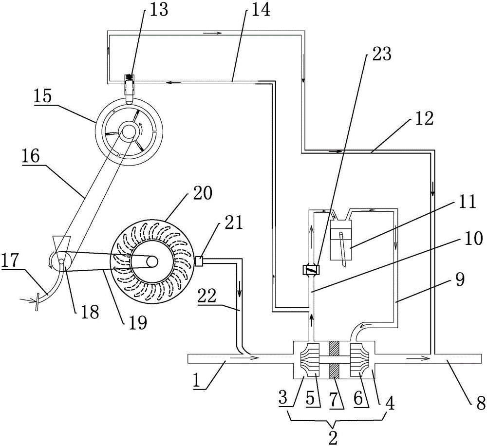
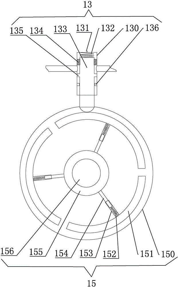
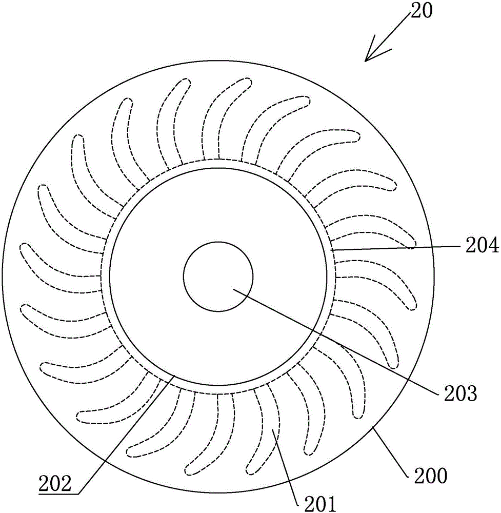
[0032] attached Figure 1-6 The components corresponding to the reference signs in the figure are: front intake pipe 1, exhaust gas turbocharger 2, intake cavity 3, exhaust cavity 4, intake turbine 5, exhaust turbine 6, partition 7, exhaust Pipe 8, exhaust manifold 9, rear intake pipe 10, cylinder block 11, gas inlet pipe 12, gas valve 13, gas outlet pipe 14, centrifugal controller 15, belt one 16, accelerator pedal 17, driving wheel 18, Belt two 19, air blower 20, one-way valve 21, air supply pipe 22, throttle valve 23; valve housing 130, air vent 131, control spring 132, valve core 133, sealing ring 134, limit block 135, positioning block 136; Housing 150, sector block 151, connecting spring 152, sliding sleeve 153, sliding rod 154, large runner 155, small runner 156; casing 200, blade 201, air inlet 202, driven wheel 203, impeller 204, one-way clutch One 157, one-way clutch two 205; throttle housing 231, throttle shaft 232, flap 233.

[0033]The exhaust gas turbocharger 2...

Embodiment 2

[0046] On the basis of Embodiment 1, there are the following modifications in this embodiment:

[0047] As another implementation of the flow control device, the flow control device includes an electric gas valve, and the gas inlet and outlet ports of the electric gas valve are respectively connected to the adjacent ends of the gas inlet pipe 12 and the gas outlet pipe 14; the electric gas valve is provided by the engineer. The vehicle controller controls its opening, and the engineering vehicle controller (that is, the central processing unit that controls the engineering vehicle) detects the state of the accelerator pedal 17 through a sensor, and then controls the opening of the electric gas valve; When the pedal 17 is changed from the depressed state to the relaxed state, the electric gas valve is controlled to guide an appropriate amount of gas from the gas outlet pipe 14 into the gas introduction pipe 12 . The greater the clockwise speed when the accelerator pedal 17 is r...


PUM


Abstract

The invention relates to an engineering vehicle adopting an exhaust turbocharging auxiliary device. The exhaust turbocharging auxiliary device comprises a gas leading-out pipe and a gas leading-in pipe, wherein the gas leading-out pipe is in sealing communication with a rear gas inlet pipe, and the gas leading-in pipe is in sealing communication with an exhaust pipe; a flow control device body is connected to the position between the adjacent ends of the gas leading-in pipe and the gas leading-out pipe in a sealing mode and is controlled by an accelerator pedal on one side of the flow control device body; when the accelerator pedal is released, the flow control device body is suitable for leading appropriate gas into the gas leading-in pipe from the gas leading-out pipe, compressed gas in the rear gas inlet pipe is directly led into the exhaust pipe through a pipeline and the flow control device body, and the gas leading-in amount is adjusted by the flow control device body according to the rotating speed of the accelerator pedal; and when the accelerator pedal is trodden to move, appropriate external air is fed into a front gas inlet pipe by an air feeder according to the rotating speed of the accelerator pedal; and accordingly, the power of an engine can be immediately reduced along with releasing of the accelerator pedal, and the turbine time lag is decreased.

Description

technical field [0001] The invention relates to an exhaust gas turbocharging auxiliary device, an engineering vehicle using the device (especially an engineering vehicle using a gasoline or diesel engine) and a method for reducing turbo time lag, which can reduce the turbo time lag effect. Background technique [0002] At present, as people's awareness of environmental protection increases, fuel-efficient and powerful engines are becoming more and more popular, and small-displacement exhaust gas turbocharged engines have become the main equipment on today's engineering vehicles. However, the exhaust gas turbocharger has a time-lag effect, because the supercharging effect of the exhaust gas turbocharger is mainly generated by the intake turbine located in the intake passage, and the intake turbine is driven by the exhaust turbine located in the exhaust passage, The speed of the exhaust turbine is determined by the exhaust pressure of the engine. When the driver suddenly steps...

Claims


Application Information

Patent Timeline
IPC IPC(8): F02B37/12F02B37/16F02B37/02F02D29/02
CPCY02T10/12
Inventor 不公告发明人
Owner 李雯雯
Learn More