
Device and method suitable for drilled hole form drawing and intra-hole obstacle taking

A hole type and hole technology, applied in earthwork drilling, measurement, wellbore/well parts, etc., can solve problems such as unstable contact, reduced drilling efficiency, and easy falling off of objects

Active Publication Date: 2016-10-12
HOHAI UNIV
View PDF5 Cites 7 Cited by
  • Summary
  • Abstract
  • Description
  • Claims
  • Application Information

AI Technical Summary

Problems solved by technology

But this method has the following disadvantages: (1) the efficiency of the diamond head to wear hard objects is extremely low, and the cylinder diameter of the diamond head is all certain. When encountering larger objects such as bricks, the success of using the diamond head The rate will be greatly reduced; (2) in the process of taking out the diamond head from the ground, because the contact between the objects in the cylinder and the wall of the cylinder is not stable, the objects in the cylinder are very easy to fall off during the process of taking out; (3) when the underground pebbles When the hard objects such as bricks and bricks mixed with soil are taken out by the diamond head, the hard objects in the cylinder must have been bonded relatively tightly at this time, and the cylinder cavity of the diamond head has been fully blocked, which has caused great difficulty in cleaning the diamond head. Big trouble, also reduces the efficiency of drilling to a certain extent
Another example is that before monitoring the displacement of deep soil, it is necessary to drill vertical inclinometer holes and bury inclinometer pipes at the pre-selected monitoring positions on the construction site. The irreversible impact of the data not only leads to inaccurate judgments on the stability of the structure, but also lacks data guidance for the next step of construction (such as filling, rolling or heaping, etc.), and there is a certain degree of blindness

Method used


Image

  • Device and method suitable for drilled hole form drawing and intra-hole obstacle taking
  • Device and method suitable for drilled hole form drawing and intra-hole obstacle taking
  • Device and method suitable for drilled hole form drawing and intra-hole obstacle taking

Examples


Embodiment Construction

[0057] The present invention will be further described below in conjunction with the accompanying drawings. The following examples are only used to illustrate the technical solution of the present invention more clearly, but not to limit the protection scope of the present invention.

[0058] The technical scheme adopted in the present invention is as follows:

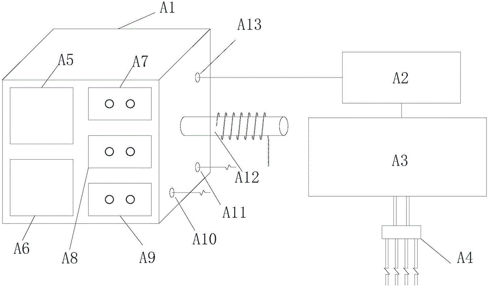
[0059] The device consists of two parts above ground and underground, namely: outside the cave visual operation module A and inside the cave fetching module B, the two parts are connected by the hoisting control area, travel control area and hydraulic control area in the outside visual operation module , the two parts are inseparable and function together as a unified whole.

[0060] The visual operation module outside the cave mainly includes console A1, oil pump A2, fuel tank A3, six-way valve A4, camera display A5, linear display A6, hoisting control area, travel control area and hydraulic control area.

[0061] I...


PUM


Abstract

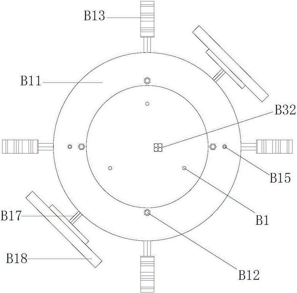
The invention discloses a device and method suitable for drilled hole form drawing and intra-hole obstacle taking. Through a dip angle inductor and methods such as infinitesimal iterated integral, the hole form three-dimensional dip angles of all positions of a vertical or inclined hole and three-dimensional coordinates of a hole form center point can be continuously obtained, and a hole form curve is accurately drawn; and through a visualization module, combined hydraulic cylinders and different types of grabbing sections, the obstacle characteristics such as the number, the size and the shape can be confirmed through a method for analyzing the stress of different obstacles and adjusting the oil pressure adjustment, and the various types of obstacles such as a large number of sediment obstacles, a small number of obstacles or a single specific obstacle can be taken out. The device comprises an extra-hole visualization operation module and an intra-hole obstacle taking module. The extra-hole visualization operation module comprises an operation table, a lifting control region, an advancing control region, a hydraulic control region, a camera display screen, a linear display screen and the like. The intra-hole obstacle taking module comprises a base, a dip angle inductor, a counter-force frame, idler wheels with motors, light emitting cameras, a drive rod, connecting rods, a drive disc, the grabbing sections and the like.

Description

technical field [0001] The invention relates to a device and method suitable for drawing hole patterns of boreholes and extracting objects in holes, and belongs to the technical field of civil engineering construction and monitoring. Background technique [0002] Vertical or inclined drilling is often required in civil engineering construction, and most of them use mechanical drilling. For example, inclined drilling is often required for slope or foundation pit support, and often the design does not allow changing the hole position coordinates. After drilling, due to different geological conditions, the soil and rocks in the hole often collapse, resulting in the anchor rod not being able to enter the hole smoothly. At present, there are few treatment methods for the collapsed soil and rock blocks in the cave, and most of them are for the sediment. When there are few soil and rock obstacles in the cave, these treatment methods are not only relatively cumbersome, time-consumin...

Claims


Application Information

Patent Timeline
IPC IPC(8): E21B47/00E21B47/002E21B31/18
CPCE21B31/18E21B47/00E21B47/002
Inventor 刘鑫赵四汉单浩徐奋强甘亮琴洪宝宁
Owner HOHAI UNIV
Learn More