


Quick Research
Generate reliable direction feasibility study reports for your R&D in just a few steps.

Technical Q&A
Discover and master advanced knowledge NOW. Basics, ideas, possibilities, all at once.

Find Solutions
As an expert in R&D theories, this can generate solutions to your technical problems instantly.

Evaluate Feasibility
Analyze your overall solution with one click, know your potential R&D risks in advance.

Monitor Landscape
Get weekly tech updates, stay abreast of the latest tech innovations and key insights.
Automatic die opening device used for optical lenses
An optical lens and automatic technology, applied in the field of automatic mold opening devices, can solve the problems of low mold opening efficiency and low yield, and achieve the effects of saving space, avoiding waste, and reducing bumps and scratches
- Summary
- Abstract
- Description
- Claims
- Application Information
AI Technical Summary
Problems solved by technology
Method used
Image

Examples
Embodiment 1
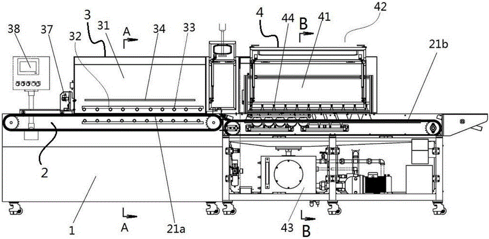
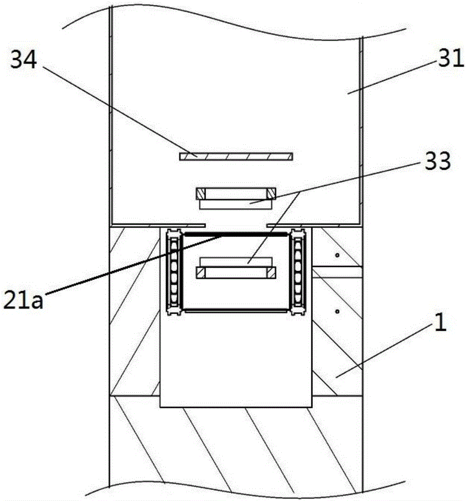
[0028] The invention discloses an automatic mold opening device for optical lenses, such as Figure 1 to Figure 3 Shown, comprise frame 1, conveying unit 2, heating unit 3, cooling unit 4, controller, wherein, controller is PLC controller, conveying unit 2 comprises the mesh conveyor belt that is horizontally arranged on frame 1, conveys The driving mechanism, the heating unit 3 includes a tunnel oven 31, a heating system 32 is arranged in the box of the tunnel oven 31, and the cooling unit 4 includes a tunnel cooling box 41, and a cold source system is arranged in the box of the tunnel cooling box 41 42. The mesh conveyor belt passes through the tunnel oven 31 and the tunnel cooling box 41 sequentially, and the conveying drive mechanism, heating system 32, and cold source system 42 are all connected to the PLC controller.
[0029] The preferred mode of the present invention is that the heating system 32 includes several infrared lamps 33 and temperature measuring sensors 37, ...
Embodiment 2
[0035] The present invention provides an automatic mold opening device of another embodiment, such as figure 1 , Figure 4 As shown, the difference from Embodiment 1 is that in this embodiment, the heating system 32 also includes a heat source buffer plate 34, a heat circulation fan 35, and an exhaust fan 36, and the heat source buffer plate 34 is arranged on the wall of the tunnel oven 31 Between the infrared lamp tube 33, it is used to accumulate heat for the heating time of the heating system.
[0036] Heat circulation blower 35, exhaust blower 36 are arranged on the casing top of tunnel oven 31, and heat circulation blower 35 is used for circulating the air flow in described tunnel oven 31 casings, and exhaust blower 36 is used for communicating with described tunnel oven 31 The air inside the box and the air outside the box.
[0037] By setting the heat circulation fan 35, the hot air in the tunnel oven 31 can circulate in the oven, so that the temperature in the oven i...
Embodiment 3
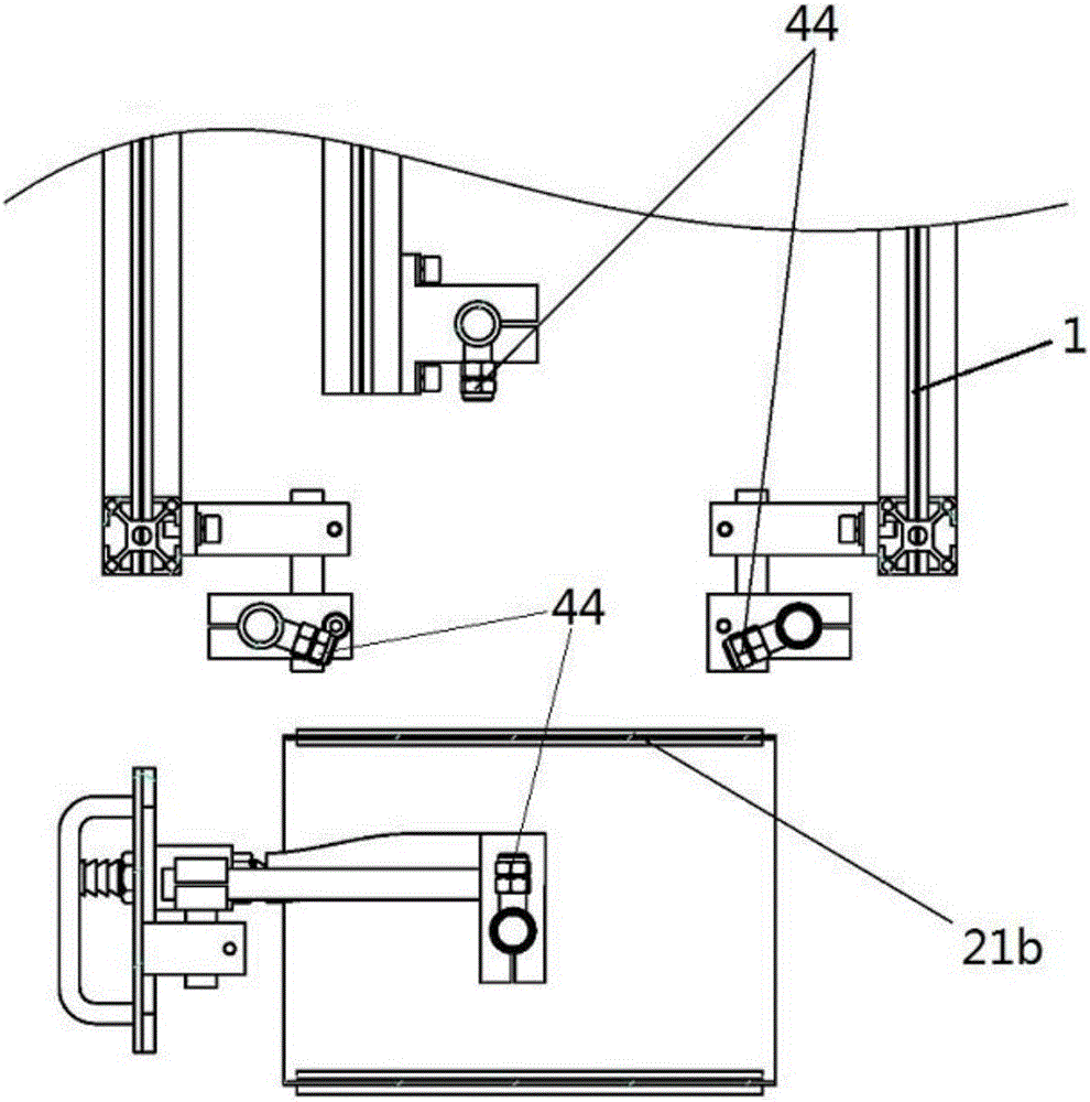
[0039] The present invention provides an automatic mold opening device of another embodiment, such as figure 1 As shown, the difference from Embodiment 1 is that in this embodiment, the conveying unit includes a first mesh conveyor belt 21a and a second mesh conveyor belt 21b that operate independently, and the first mesh conveyor belt 21a passes through The casing of the tunnel oven 31, the second mesh conveyor belt 21b passes through the tunnel cooling box 41 casing, the outlet end of the first mesh conveyor belt 21a is connected with the inlet end of the second mesh conveyor belt 21b, The first mesh conveyor belt 21a and the second mesh conveyor belt 21b are respectively driven and operated by two driving motors connected to the PLC controller.
[0040] see Figure 5 , Image 6 As shown, the first mesh conveyor belt 21a and the second mesh conveyor belt 21b are connected through a transition mechanism 7, and the transition mechanism 7 includes a connecting plate 71, a gui...
PUM
 Abstract
Description
Claims
Application Information
 - R&D Engineer
- R&D Manager
- IP Professional
- Industry Leading Data Capabilities
- Powerful AI technology
- Patent DNA Extraction
Browse by: Latest US Patents, China's latest patents, Technical Efficacy Thesaurus, Application Domain, Technology Topic, Popular Technical Reports.
© 2024 PatSnap. All rights reserved.Legal|Privacy policy|Modern Slavery Act Transparency Statement|Sitemap|About US| Contact US: help@patsnap.com