Eureka AIR delivers breakthrough ideas for toughest innovation challenges, trusted by R&D personnel around the world.

Cylindrical roller bearing and bearing device for transmission

A cylindrical roller and bearing technology, which is applied in the field of cylindrical roller bearings and bearing devices for transmissions, can solve problems such as limitations and larger sizes, and achieve the effects of suppressing burnout, suppressing edge loads, and realizing miniaturization

Inactive Publication Date: 2016-10-05
NSK LTD
View PDF12 Cites 4 Cited by
  • Summary
  • Abstract
  • Description
  • Claims
  • Application Information

AI Technical Summary

Problems solved by technology

In this case, a cylindrical roller bearing can be used to greatly reduce the size, but the other ball bearing needs to support thrust loads in both directions, and the size tends to increase, which may be affected by the layout of the unit. limit

Method used


Image

  • Cylindrical roller bearing and bearing device for transmission
  • Cylindrical roller bearing and bearing device for transmission
  • Cylindrical roller bearing and bearing device for transmission

Examples


Embodiment

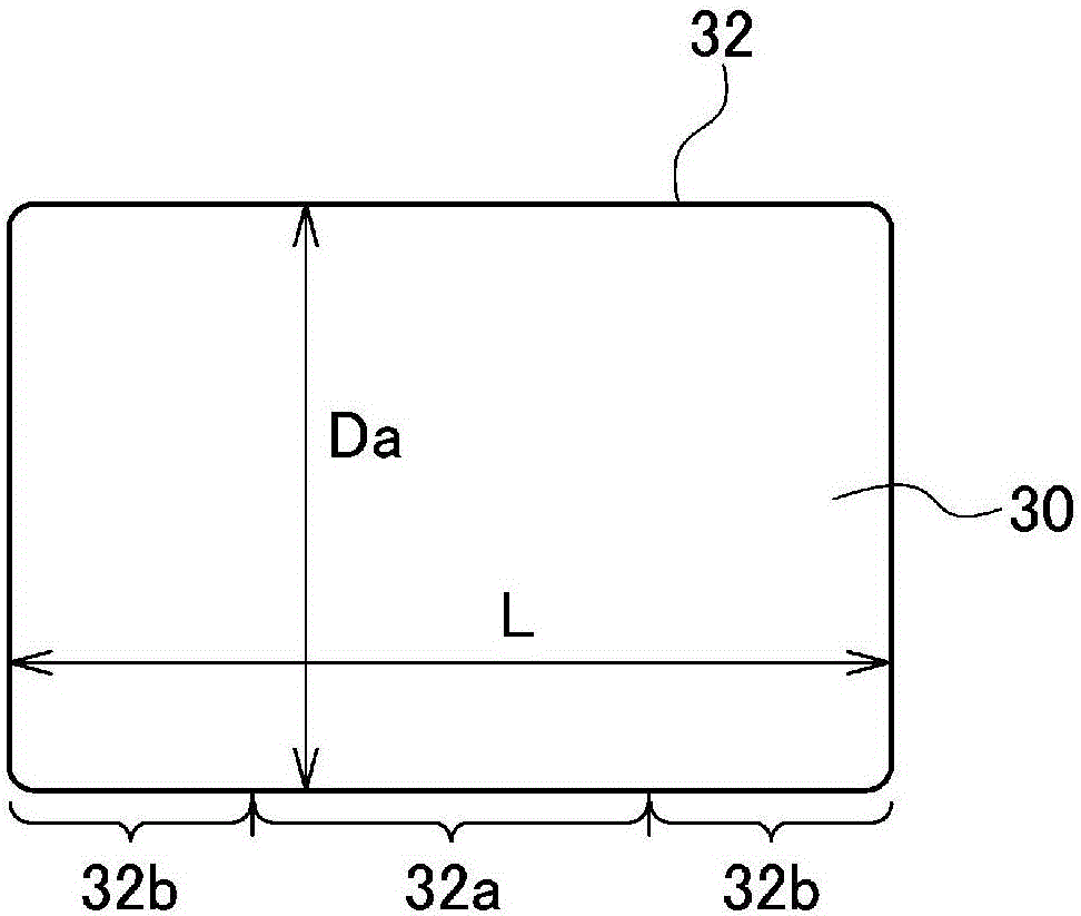
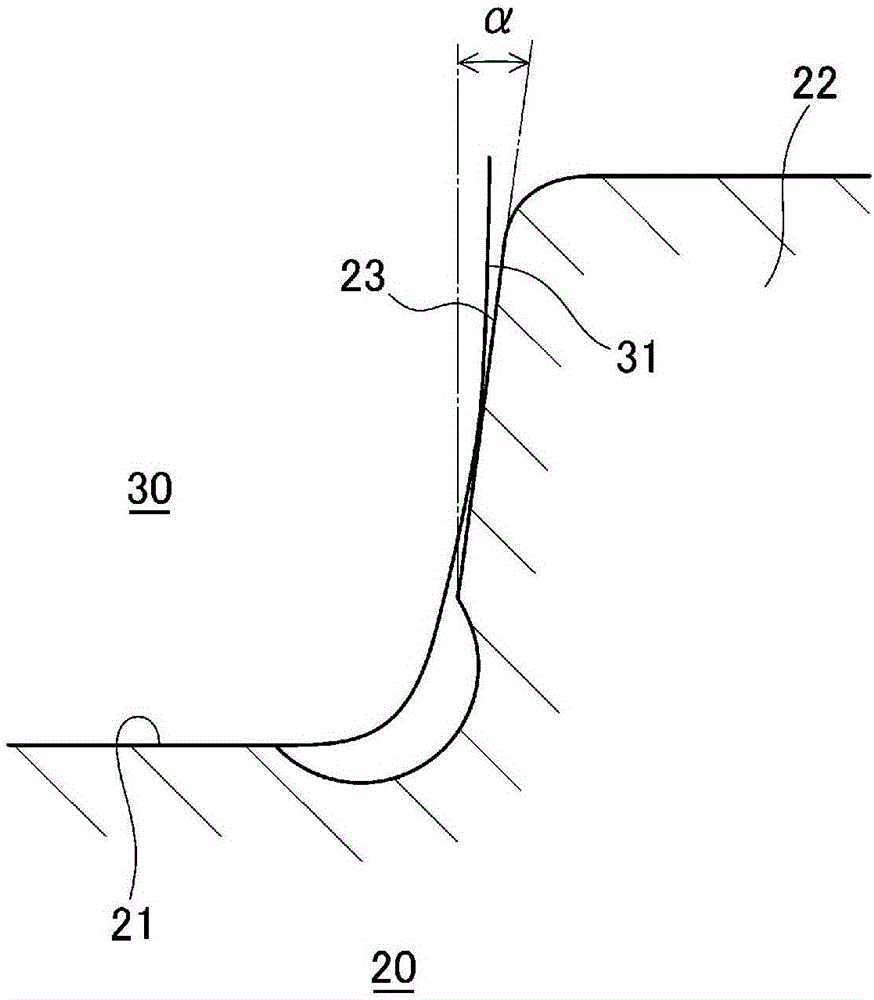
[0081] Here, with regard to the cylindrical roller bearing 1 of the present embodiment, verification experiments were performed while changing the shape of the rolling surface 32 of the cylindrical roller 30 to confirm the effect thereof. In addition, the verification experiment was performed under the following conditions, and the target lifetime was 120 Hrs.

[0082] Verify experimental conditions

[0083] Load: 0.4C (C: basic rated dynamic load)

[0084] Speed: 3000rpm

[0085] Lubrication conditions: ATF, 120°C, oil bath

[0086] Foreign matter: 0.05g / L: (Foreign matter size: 10-50μm, iron)

[0087] Tilt: 0rad (no tilt), 3 / 1000rad (with tilt)

[0088] [Table 1]

[0089]

[0090] Table 1 shows the experimental results in the case of using the cylindrical roller 30 in which the rolling surface 32 was crowned with a single arc. It can be confirmed from Table 1 that if the radius of curvature is 300 to 700 mm, the target life can be achieved even if there is a relativ...


PUM


Abstract

A cylindrical roller bearing (1) is provided with an outer race (10), an inner race (20), and a plurality of cylindrical rollers (30). The outer race (10) has on the inner peripheral surface thereof an outer-race raceway surface (11) and a pair of outer-race flanges (12) provided on both axial-direction sides of the outer-race raceway (11). The inner race (20) has on the outer peripheral surface thereof an inner-race raceway (21) and an inner race flange (22) provided on one axial-direction side of the inner-race raceway (21). The cylindrical rollers (30) are arranged between the outer-race raceway (11) and the inner-race raceway (21). The radial-direction height (A) of the outer-race flanges (12) is greater than the radial-direction height (B) of the inner-race flange (22). The radial-direction gap (C) between the outer-race flanges (12) and the inner-race flange (22) is set to 2 mm or less. Consequently, the incidence of edge loading due to a thrust load is minimized and the state of lubrication inside the bearing is improved, which makes it possible to markedly reduce the size of a highly durable cylindrical roller bearing and transmission.

Description

technical field [0001] The present invention relates to a cylindrical roller bearing and a bearing device for a transmission. Background technique [0002] From the viewpoint of improving the mileage per unit fuel, it is strongly required to reduce the size and improve the efficiency of automobile transmissions. Generally speaking, compared with the tapered roller bearings used for preloading, ball bearings have much smaller torque and are mostly used in transmissions, but they are easy to increase in size, and in some cases, they are limited. For example, as a bearing supporting a gear, in some cases, one is a cylindrical roller bearing used without preloading, and the other is a ball bearing, and the ball bearing is used to withstand the thrust in both directions due to the meshing of the gears. Load, and the cylindrical roller bearing supports only radial load support structure. In this case, a cylindrical roller bearing can be used to greatly reduce the size, but the o...

Claims


Application Information

Patent Timeline
Patent Type & Authority Applications(China)
IPC IPC(8): F16C33/58F16C19/26F16C19/36F16C33/34F16C33/66F16H57/04
CPCF16C19/225F16C19/26F16C33/34F16C33/585F16C33/767F16C2240/40F16C2240/46F16C2240/50F16C2240/70F16C2361/63F16H57/04F16H57/0471
Inventor 加藤晃嗣田中进浅见哲也上村和宏
Owner NSK LTD
Why Eureka
Eureka Blog
Learn More