Eureka AIR delivers breakthrough ideas for toughest innovation challenges, trusted by R&D personnel around the world.

A non-uniformity correction method for a maskless infrared thermal imager

A non-uniformity correction, infrared thermal imaging camera technology, applied in the direction of instruments, image enhancement, scientific instruments, etc., can solve the problems of not considering the influence of the output response of the infrared detector, not solving the nonlinearity of the infrared detector, etc., to achieve increased Quantity, precision of results, effect of resolving non-uniformities

Inactive Publication Date: 2019-07-12
NANJING UNIV OF SCI & TECH
View PDF6 Cites 0 Cited by
  • Summary
  • Abstract
  • Description
  • Claims
  • Application Information

AI Technical Summary

Problems solved by technology

In this way, the ambient temperature can also be taken into account, that is, when the substrate temperature drifts, the ambient temperature also drifts. At this time, the background needs to be re-calibrated, so the shutterless technology completes the work of correcting the background at any time and overcomes the temperature drift. However, this method does not consider the influence of different real targets on the output response of the infrared detector, and still does not solve the problem caused by the nonlinearity of the infrared detector. It can only be regarded as a one-point calibration algorithm. When the temperature difference is large, the non-uniformity caused by this nonlinearity becomes more obvious

Method used


Image

  • A non-uniformity correction method for a maskless infrared thermal imager
  • A non-uniformity correction method for a maskless infrared thermal imager
  • A non-uniformity correction method for a maskless infrared thermal imager

Examples


Embodiment 1

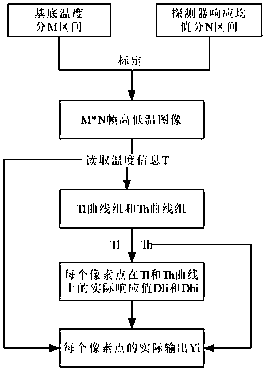
[0047] A non-uniformity correction method for a maskless infrared thermal imager, the specific method steps are as follows:

[0048] A 336×256-pixel uncooled vanadium oxide thermal imaging camera was used to collect infrared images with a frame rate of 25 frames per second.

[0049] First, place the infrared thermal imaging camera in a temperature-controllable environment, divide the temperature into 20 intervals according to the working temperature range of the detector, adjust the ambient temperature so that it is at an end point of the temperature interval, and wait for the detector to work stably. The temperature is convenient for the ambient temperature to be the same, and the detector base temperature is correspondingly divided into 20 intervals. Then, let the thermal imager shoot a uniform object with variable temperature (such as a black body), change the temperature of the black body, and the output response value of the detector will also change accordingly. By adjus...


PUM


Abstract

The invention discloses a non-uniformity correction method of a non-barrier infrared thermal imaging system. The method comprises the steps of: dividing a substrate temperature into M intervals according to a substrate temperature range, shooting black bodies of different temperatures in each temperature interval, dividing original output of a detector into N intervals, calibrating M*N frames of images, and storing the images; then, according to the substrate temperature, reading the calibrated M frames of images above and below the substrate temperature by the detector; and subsequently, according to a response value of each pixel point, determining corresponding values of two temperature curves above and below the substrate temperature, carrying out weighted calculation based on the substrate temperature, and obtaining a final output value. According to the invention, barriers are successfully removed in interval division of the substrate temperature in the calibration process, the non-uniformity caused by output non-linearity of the detector is also considered, and interval division is also carried out the original output of the detector, so that secondary calibration is not needed after all images are calibrated, a once for all effect is achieved, and the influences of non-uniformity caused by the non-linearity of the infrared detector are also solved.

Description

technical field [0001] The invention belongs to the field of video image enhancement, and in particular relates to a method for correcting non-uniformity of an infrared thermal imager without a shield. Background technique [0002] In the early 18th century, infrared light beyond the visible spectrum was discovered. After more than two hundred years of development and research, the application of infrared spectroscopy has made great progress. Infrared imaging systems developed slowly from the crude single-pixel detection equipment in the early days to the more advanced liquid nitrogen or complex cooling microbolometer systems in the late 1980s. At that time, the systems were expensive and not portable, making The application of the movement has remained in important fields such as national defense and aerospace for many years. [0003] With the development of technology, the performance of detectors, movement and software system has been improved to a certain extent, and th...

Claims


Application Information

Patent Timeline
Patent Type & Authority Patents(China)
IPC IPC(8): G01J5/52G06T5/00
Inventor 隋修宝陶远荣陈钱顾国华刘源高航匡小冬潘科辰沈雪薇孙毅诚
Owner NANJING UNIV OF SCI & TECH
Why Eureka
Eureka Blog
Learn More