
Efficient air preheating method and preheater

An air preheater, high-efficiency air technology, applied in the direction of heat exchanger type, indirect heat exchanger, heat exchange equipment, etc., can solve the problems of uncompact equipment, small heat exchange plate gap, small heat transfer area, etc. Compact equipment, high efficiency, reduced dust accumulation, and large heat transfer area

Inactive Publication Date: 2016-10-05
刘英聚
View PDF0 Cites 6 Cited by
  • Summary
  • Abstract
  • Description
  • Claims
  • Application Information

AI Technical Summary

Problems solved by technology

[0002] Furnaces and other equipment are usually equipped with air preheaters to improve thermal efficiency. Commonly used air preheaters include nail head tube type, heat pipe type, plate type, and cast iron type. Tube-air way of heat transfer, small heat transfer area, not compact equipment, there is a leeward side when the tubes are staggered, the pressure drop is large, and there is a vortex area on the leeward side, causing dust to adsorb and accumulate on the tube wall in this area, and it is not easy to remove
The plate air preheater has a small gap between the heat exchange plates, which is a "precision" equipment and is suitable for clean media. If the flue gas has a high dust content, it is easy to accumulate dust or even clog it, and it is not easy to remove
Cast iron air preheater has small heat transfer area, heavy weight and not compact

Method used


Image

  • Efficient air preheating method and preheater
  • Efficient air preheating method and preheater

Examples


Embodiment Construction

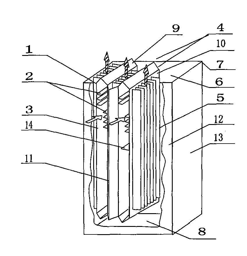
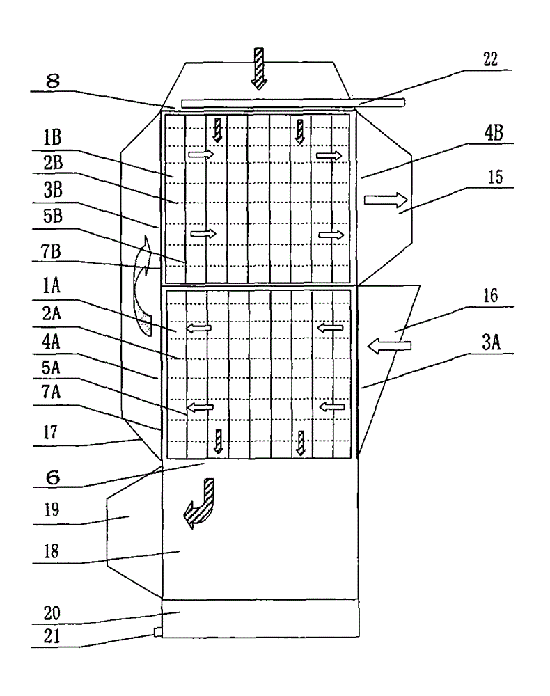
[0020] See figure 1 , is a single-box air preheater, which is applied to a flue gas air preheater with no or low sulfide. The shell 7 includes a front plate / rear plate 12 and two side plates 13. Inside the shell 7, several vertical flat Tube heat exchange unit; vertical flat tube heat exchange unit is composed of vertical flat tube 1, inner longitudinal large fins 2 and outer longitudinal large fins 5, vertical flat tube 1 consists of 2 panels 10 and 2 end plates 9 The end plate 9 is a wedge-shaped folded plate, the inner longitudinal large fins 2 and the outer longitudinal large fins 5 are arranged on both sides of the panel 10, and a connecting rib 14 is also provided between the two panels 10; two adjacent vertical flat The long side of the open end of the tube 1 is connected with a wedge-shaped bridge plate 11, and is connected and communicated with the front plate / rear plate 12; The end plate side of the vertical flat tube 1 is the inlet and outlet of the shell side, whi...


PUM

PropertyMeasurementUnit
thicknessaaaaaaaaaa
heightaaaaaaaaaa
thicknessaaaaaaaaaa

Abstract

The invention provides an efficient air preheating method and belongs to the field of the energy saving technology. By means of the efficient air preheating method, the problems that an air preheater is not compact, gas interference and gas leakage happen, and dust is likely to be accumulated and difficult to remove are solved. The preheater comprises high-temperature smoke inlet and low-temperature smoke outlet channels and low-temperature air inlet and high-temperature air outlet channels. The efficient air preheating method and the preheater are characterized in that the smoke channels and the air channels are designed independently and are adjacent alternately in a flat mode; and large fins are longitudinally arranged on each channel in the air flow direction. The heat transfer area is enlarged, the equipment efficiency is improved, smoke and air flow smoothly, the resistance is reduced, the lee side is omitted, and the dust accumulation degree is substantially reduced. The invention further provides vertical flat tubes and inner-outer longitudinal large fin equipment which are used for implementing the efficient air preheating method. By the adoption of the efficient air preheating method, the heat transfer area is large, the pressure drop is small, the efficiency is high, dust accumulation is unlikely to happen, gas interference and gas leakage are avoided, cleaning is easy, and the thermal efficiency of a heating furnace can be remarkably improved.

Description

technical field [0001] The invention belongs to the technical field of energy saving, and in particular relates to a high-efficiency air preheating method and a preheater. Background technique [0002] Furnaces and other equipment are usually equipped with air preheaters to improve thermal efficiency. Commonly used air preheaters include nail head tube type, heat pipe type, plate type, and cast iron type. Tube-air way of heat transfer, the heat transfer area is small, the equipment is not compact, there is a leeward side when the tubes are staggered, the pressure drop is large, and there is a vortex area on the leeward side, causing dust to adsorb and accumulate on the tube wall in this area, and it is not easy to remove. The plate air preheater has a small gap between the heat exchange plates, which is a "precision" equipment and is suitable for clean media. If the flue gas has a high dust content, it is easy to accumulate dust or even clog it, and it is not easy to remove....

Claims


Application Information

Patent Timeline
Patent Type & Authority Applications(China)
IPC IPC(8): F28D9/02F28F21/00F28F3/00F28F19/02F28G9/00
Inventor 刘英聚
Owner 刘英聚
Learn More