Eureka AIR delivers breakthrough ideas for toughest innovation challenges, trusted by R&D personnel around the world.

Fireproof explosion-proof combination structure at power cable joint of electric power system and application method

A technology of cable joints and power systems, which is applied in the direction of cable joints, etc., can solve the problems of poor durability and low manufacturing cost, and achieve the effect of solving the effects of poor durability and reliability of fire protection performance, low manufacturing cost, and improving economy

Active Publication Date: 2016-09-28
WUHAN HANYUAN JIJI ELECTRIC POWER EQUIP
View PDF7 Cites 10 Cited by
  • Summary
  • Abstract
  • Description
  • Claims
  • Application Information

AI Technical Summary

Problems solved by technology

[0006] Aiming at the defect of poor durability of the existing fire and explosion protection measures for the cable intermediate joints in the power system, the present invention proposes a fire and explosion-proof combination structure at the cable joint of the power system and its use method, which aims at the main cause of the cable burning. Basically, flame retardant and explosion-proof treatment is carried out on the cable joints, which can maintain reliable fire-proof and explosion-proof performance after long-term operation, significantly reduce the safety hazard caused by cable burning, and the manufacturing cost is low, which is conducive to widespread promotion

Method used


Image

  • Fireproof explosion-proof combination structure at power cable joint of electric power system and application method
  • Fireproof explosion-proof combination structure at power cable joint of electric power system and application method
  • Fireproof explosion-proof combination structure at power cable joint of electric power system and application method

Examples


Embodiment Construction

[0054] In order to facilitate the understanding of the technical content of the present invention, the technical solutions thereof will be further described below in conjunction with the accompanying drawings.

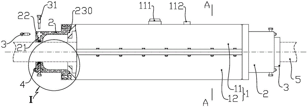
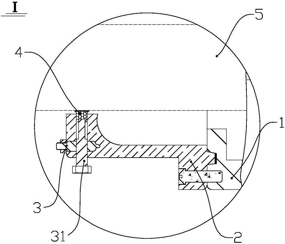
[0055] Such as figure 1 The shown fireproof and explosion-proof structure at the intermediate joint of a cable includes an outer box body 1 formed by fastening the upper half outer box 11 and the lower half outer box 12, an assembly end cover 2 connected to the left and right ports of the outer box body 1, and The insert plate 3 and the seal 4 are arranged on the assembly end cover 2 .

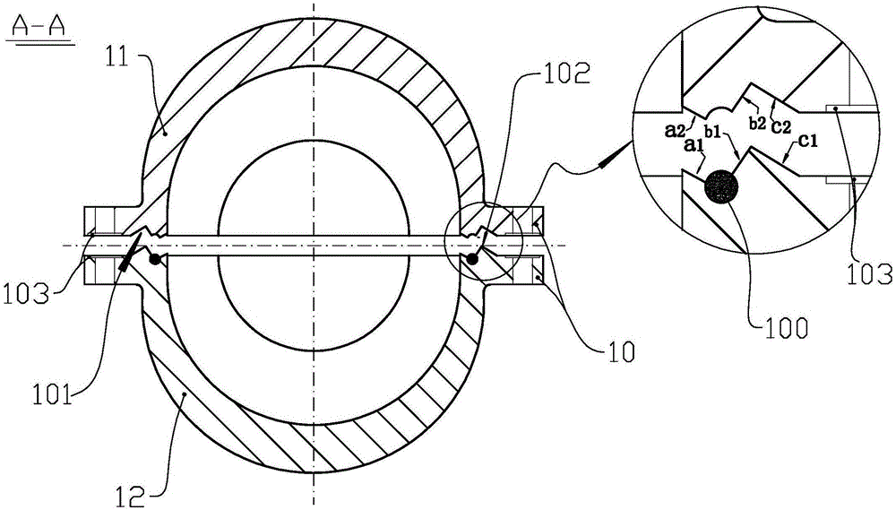
[0056] Such as figure 1 , image 3 As shown, corresponding mold grooves are provided on the upper half outer box 11 and the lower half outer box 12, and axially extending flanges 10 are respectively arranged on both sides of the transverse ports of the mold grooves. The groove here is as image 3 The settings shown are semicircular. On the lower end surface of the flange 10 of the...


PUM


Abstract

The invention discloses a fireproof explosion-proof combination structure at a power cable joint of an electric power system and an application method, belonging to the power cable connector fireproof explosion-proof combination structure. The fireproof explosion-proof combination structure at the power cable joint of the electric power system comprises an outer box body with double sealing structures on a longitudinal assembling surface, an assembling end cap which adopts an embedding sealing structure with the outer box body and a plugging board and a sealing member which seal a gap between related fitting surfaces of a cable annular surface and an assembling end cap, wherein the plugging board and the sealing member are arranged on the assembling end cap; the outer box is provided with a glue injection tube and an exhaust pipe are arranged on the outer box; the cable is fully wrapped by a power cable fireproof pack after connected to a middle connector and is arranged in the outer box; and fireproof sealing glue is injected to the outer box through the glue injection tube. In operation, air in the outer box is discharged through carbon dioxide or nitrogen and the fireproof sealing glue is injected inside the outer box and then high pressure shape forming is performed. The pressure maintaining shape forming is performed on the fireproof sealing glue by virtue of the outer box. The fireproof explosion-proof combination structure at the power cable joint realizes sealing protection on the cable connector, forms a compact filling layer on the periphery of the middle connector, solves a problem that durability and reliability of the fireproof performance are not good, and is low in manufacture cost and easy to promote.

Description

technical field [0001] The invention relates to the technical field of fireproofing and explosion-proofing of electric power system cable intermediate joints, in particular to a fire-proofing and explosion-proof composite structure at the power system cable joint and its use method. Background technique [0002] With the continuous improvement of the degree of cableization of urban power lines, the cable failure rate is also rising. Operating experience has proved that more than 80% of cable failures are related to cable accessories, and cable intermediate joint failures have the highest failure rate among cable accessories. Due to the flaws in the quality and installation process of the cable intermediate joint itself, once the cable intermediate joint explodes, it will often ignite the cable body and even damage the surrounding adjacent cables, causing huge losses to the power system. Therefore, the fire and explosion protection measures for the cable intermediate joint ar...

Claims


Application Information

Patent Timeline
Patent Type & Authority Applications(China)
IPC IPC(8): H02G15/10
CPCH02G15/10
Inventor 王光英
Owner WUHAN HANYUAN JIJI ELECTRIC POWER EQUIP
Why Eureka
Eureka Blog
Learn More