
High-precision balancing flowmeter

A flow-balanced, high-precision technology, applied to the volume/mass flow generated by mechanical effects, and the detection of fluid flow by measuring differential pressure. problems, to reduce the loss of kinetic energy, ensure accuracy, and reduce work intensity.

Inactive Publication Date: 2016-09-28
CHENGDU GUOGUANG ELECTRONICS INSTR
View PDF6 Cites 4 Cited by
  • Summary
  • Abstract
  • Description
  • Claims
  • Application Information

AI Technical Summary

Problems solved by technology

The differential pressure flowmeter is an instrument that measures the flow rate based on the differential pressure generated by the flow detection part installed in the pipeline, the known fluid conditions and the geometric dimensions of the detection part and the pipeline; however, the measurement range of this differential pressure flowmeter The range is narrow, because the flow meter signal (differential pressure) has a square function relationship, which limits the range of flow measurement
At present, the most commonly used nozzle forms of nozzle flowmeters are standard nozzles, long-neck nozzles, Venturi nozzles, etc. These throttling forms generally have the following disadvantages: the repeatability and accuracy of measurement are at the general level of flowmeters, due to many factors The influence is intricate, and the accuracy is difficult to improve; the site installation conditions are relatively high, and a long straight pipe section is required, which is generally difficult to meet, and the pressure loss is relatively large

Method used


Image

  • High-precision balancing flowmeter

Examples


Embodiment 1

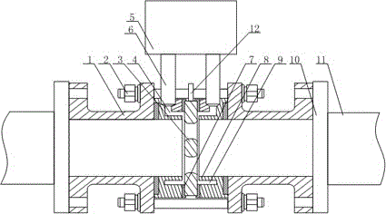
[0020] like figure 1 As shown, this embodiment includes a connecting pipe 1 with a flange, a straight pipe section 11, a sensor, two packing rings 8 and two pressure-taking pipes 6, and the adjacent ends of the two connecting pipes 1 with flanges The ends are connected together by bolts 2, and the other end of the connecting pipe 1 is connected with the straight pipe section 11 through the flange 10. On the opposite end faces of the two connecting pipes 1, packing rings 8 are arranged respectively, and the orifice plate body 3 is arranged between two pack-off rings 8. There are multiple nozzles on the orifice plate body 3, and an air passage 4 communicating with the connecting pipe 1 is opened on one side of the pack-off ring 8, and one end of the pressure-taking tube 6 is It communicates with the air passage 4, and the other end of the pressure-taking pipe 6 communicates with the sensor. On the inner wall of the other side of the packing ring 8, there is a buffer groove 9 com...


PUM


Abstract

The invention discloses a high-precision balancing flowmeter. The high-precision balancing flowmeter comprises connecting pipes, a straight pipe section, a sensor, two packer rings and two pressure measuring pipes, wherein the two connecting pipes are connected through a bolt, the other end of each connecting pipe is connected with the straight pipe section, the packer rings are arranged on the end faces of the two connecting pipes, a pore plate body is arranged between the two packer rings, and multiple nozzles are arranged on the pore plate body; an air duct communicated with the interior of the corresponding connecting pipe is formed in one side of each packer ring, one end of each pressure measuring pipe is communicated with the corresponding air duct, and the other end of each pressure measuring pipe is communicated with the sensor; a buffer groove communicated with the interior of the corresponding connecting pipe is formed in the inner wall of the other side of each packer ring; each nozzle is composed of a shrinkage section with inner diameter decreasing gradually in the flowing direction of fluid, a straight section and an enlargement section with inner diameter increasing gradually in the flowing direction of fluid, wherein the shrinkage section, the straight section and the enlargement section are connected in sequence. The connecting pipes are connected through a flange, the connecting pipes and the straight pipe section are connected through flanges, so that the practicality of the connecting pipes in measurement of different types of sensors is improved greatly, and installation and detachment can be achieved conveniently and quickly.

Description

technical field [0001] The invention relates to the field of flow measurement, in particular to a high-precision balanced flowmeter. Background technique [0002] Differential pressure flowmeter occupies the forefront of flowmeter application due to its mature technology, simple structure, stability and reliability, and wide application surface. The differential pressure flowmeter is an instrument that measures the flow rate based on the differential pressure generated by the flow detection part installed in the pipeline, the known fluid conditions and the geometric dimensions of the detection part and the pipeline; however, the measurement range of this differential pressure flowmeter The range is narrow, because the flow meter signal (differential pressure) has a square function relationship, which limits the range of flow measurement. At present, the most commonly used nozzle forms of nozzle flowmeters are standard nozzles, long-neck nozzles, Venturi nozzles, etc. These ...

Claims


Application Information

Patent Timeline
IPC IPC(8): G01F1/36G01F1/42
CPCG01F1/36G01F1/42
Inventor 吕忠贵
Owner CHENGDU GUOGUANG ELECTRONICS INSTR
Learn More