Floating quick-change end effector for deburring

An end-operator, quick-change technology, applied in tool holder accessories, manufacturing tools, chucks, etc., can solve the problems of complex structure, large limitations and high cost, and achieve small size, improved applicability, and low cost. Effect

Active Publication Date: 2018-10-09
绍兴市上虞区武汉理工大学高等研究院
View PDF7 Cites 0 Cited by
  • Summary
  • Abstract
  • Description
  • Claims
  • Application Information

AI Technical Summary

Problems solved by technology

The principle of the tool quick change module is to realize the quick change of the tool by pulling and sending the tool handle to make it contact with or loosen the taper surface of the spindle interface. The nail is connected to the hydraulic knife cylinder, and an additional hydraulic structure is required. The structure is complicated, the size is large, and the cost is high. It is only suitable for large-scale equipment and has great limitations.

Method used


Image

  • Floating quick-change end effector for deburring
  • Floating quick-change end effector for deburring
  • Floating quick-change end effector for deburring

Examples


Embodiment Construction

[0033] The present invention will be further described below in conjunction with the accompanying drawings and embodiments.

[0034] The main technical parameters of this embodiment are:

[0035]

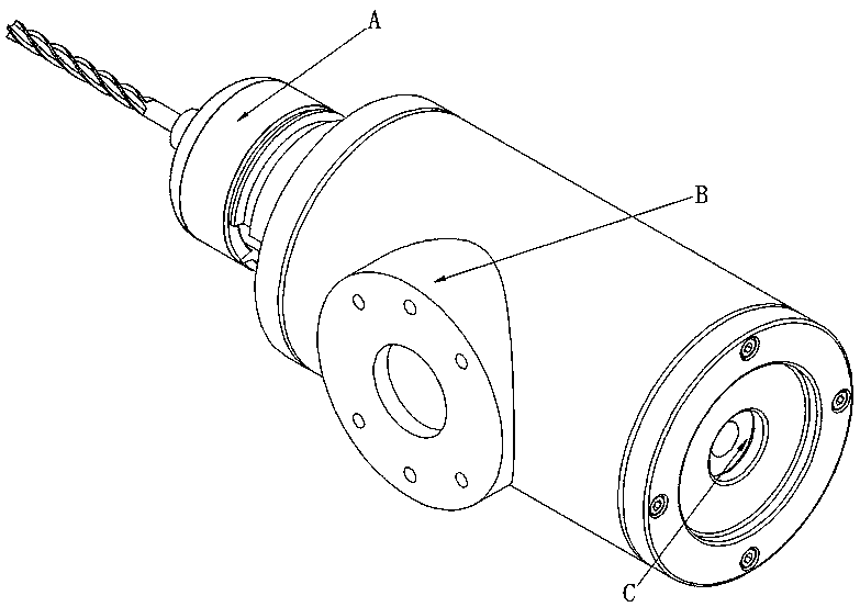
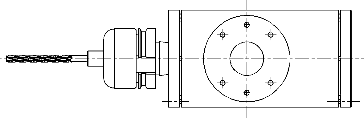
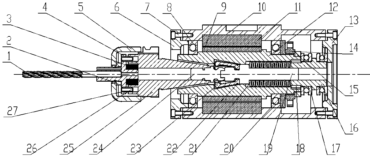
[0036] like Figure 1 to Figure 5 As shown, a floating quick-change end effector suitable for deburring includes a floating cutting module A, a spindle module B and a tool quick-changing module C; the floating cutting module A includes a tool 1, a chuck 4, an end cover 5 and Knife handle 25, one end of end cover 5 is connected and fixed with knife handle 25, the front end of chuck 4 passes through the other end of end cover 5, and the rear end is located inside end cover 5, cutting tool 1 is fixed on the front end of chuck 4, chuck 4 is connected with the handle of a knife 25 are connected by a power transmission pin 26 covered with an elastic sleeve 27, and the rear end of the collet 4 is covered with a dust-proof ring 2 and a first disc spring 3 (in this embodiment, there are ...


PUM


Abstract

The invention relates to a floating quick-change type manipulator applicable to deburring. The floating rapid-change type manipulator comprises a floating cutting module, a spindle module and a tool quick-change module, wherein the floating cutting module comprises a tool, a chuck, an end cover and a tool shank, one end of the end cover is connected and fixed with the tool shank, the front end of the chuck penetrates the other end of the end cover, the rear end of the chuck is located in the end cover, the tool is fixed at the front end of the chuck, the chuck and the tool shank are connected through a dowel pin sleeved with an elastic sleeve, a dust ring and a first disc spring are arranged at the rear end of the chuck in a sleeving manner, the dust ring is tightly pressed between a chuck flange and the end cover and blocks an opening of the end cover, and the first disc spring is tightly pressed between the chuck flange and the tool shank. The manipulator realizes floating machining in a purely mechanical manner, pneumatic or hydraulic spindles in multiple directions are not required to be arranged, the manipulator is simple in structure, small in size and applicable to a robot platform, the applicability is improved, and the cost is low.

Description

technical field [0001] The invention belongs to the field of end effectors, in particular to a floating quick-change end effector suitable for deburring. Background technique [0002] The debris and tiny microscopic metal particles on the surface of metal parts are called burrs. Burrs will not only directly reduce the precision and appearance quality of the parts themselves, but also weaken their performance and life. Therefore, deburring is regarded as a separate Processing technology is particularly important. Automated deburring with the help of industrial robots is a high-precision, high-efficiency deburring process, that is, an end effector is installed at the end of the industrial robot, and the industrial robot drives the end effector to complete the specified deburring work according to the prescribed procedure. [0003] The end effector generally includes a cutting module, a spindle module and a tool quick change module. The cutting module is used to install the to...

Claims


Application Information

Patent Timeline
Patent Type & Authority Patents(China)
IPC IPC(8): B25J11/00B25J15/00B23Q3/12B23B31/00B23B19/02B23C3/12
CPCB23B31/006B23C3/12B23Q1/70B23Q3/12B25J11/006B25J15/0019
Inventor 陈满意李杰
Owner 绍兴市上虞区武汉理工大学高等研究院
Why Eureka
Try Eureka