
cables for radio frequency therapy equipment

A therapeutic device and cable technology, applied in the field of wire and cable, can solve the problems of poor site cleanliness, increased disinfection workload, and increased difficulty in management and maintenance, and achieve improved cleanliness, good soft bending effect, and excellent chemical corrosion resistance Effect

Active Publication Date: 2017-05-10
SUZHOU CABLEPLUS PHOTOELECTRIC TECH
View PDF7 Cites 0 Cited by
  • Summary
  • Abstract
  • Description
  • Claims
  • Application Information

AI Technical Summary

Problems solved by technology

[0004] In order to save the investment cost of medical facilities and reduce the cost of radiofrequency treatment for patients, most of the industrial countries meet the requirements for the use of radiofrequency therapeutic equipment in the form of decentralized connection. The power line, network cable and signal line are connected to the corresponding interface of the radio frequency therapeutic instrument as an independent unit. Although this method can significantly reduce the facility cost, it has the following shortcomings: first, the cleanliness of the site where the radio frequency therapeutic instrument is used is poor; Second, the difficulty of management and maintenance has increased; third, the workload of disinfection has doubled; fourth, safety has been affected

Method used


Image

  • cables for radio frequency therapy equipment

Examples


Embodiment 1

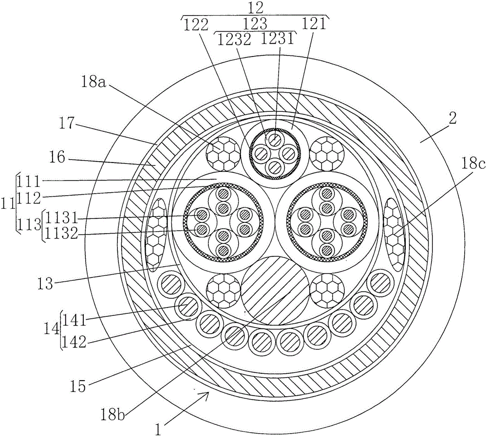
[0021] See figure 1 , showing a cable core 1 and an outer sheath 2 extruded outside the cable core 1, the cable core 1 includes a network cable 11, a signal transmission line 12, an inner winding cladding 13, a power transmission line 14, an intermediate winding The cladding layer 15, the shielding layer 16 and the outer wrapping layer 17, the network line 11 and the signal transmission line 12 accompany each other and the inner filler 18a and A reinforcement 18b, the reinforcement 18b is separated from the signal transmission line 12 by 180° around the circumferential direction of the cable core 1, that is to say, the signal transmission line 12 and the reinforcement 18b correspond to each other across the network line 11, and the network line 11, signal The transmission line 12, the inner filling member 18a and the reinforcing member 18b are located in the inner wrapping layer 13, and the number of power transmission lines 14 is plural and arranged in a circular arc around t...

Embodiment 2

[0032] Only change the shielding layer 112 of the network cable to braided tinned copper wire with a single wire diameter of 0.3 mm, and the braiding density is changed to 95%; change the shielding layer 122 of the signal transmission line to tinned copper wire with a single wire diameter of 0.2 mm The braiding structure and the braiding density are changed to 91%; the shielding layer 16 is changed to a tinned copper wire braid with a single wire diameter of 0.35mm, and the braiding density is changed to 85%. All the other are the same as the description to embodiment 1.

Embodiment 3

[0034] Only change the shielding layer 112 of the network cable to braided tinned copper wire with a single diameter of 0.2mm, and the braiding density is changed to 91%; change the shielding layer 122 of the signal transmission line to tinned copper wire with a single diameter of 0.1mm The braiding structure and the braiding density are changed to 95%; the shielding layer 16 is changed to a tinned copper wire braid with a single wire diameter of 0.15mm, and the braiding density is changed to 95%. All the other are the same as the description to embodiment 1.

[0035] To sum up, the technical solution provided by the present invention solves the technical problems in the prior art, completes the task of the invention, and faithfully realizes the technical effect recorded by the applicant in the above technical effect column.


PUM

PropertyMeasurementUnit
diameteraaaaaaaaaa
diameteraaaaaaaaaa
diameteraaaaaaaaaa

Abstract

A cable for radio frequency treatment equipment belongs to the technical field of wires and cables for medical equipment. Including the cable core and the outer sheath extruded outside the cable core. The cable core includes network cables, signal transmission lines, inner wrapping layer, power transmission line, intermediate wrapping layer, shielding layer and outer wrapping layer. Network cables and signal transmission lines Accompanying each other, inner fillers and reinforcements are provided in the space between the network cable and the signal transmission line. The network cable, signal transmission line, inner filler and reinforcement are located in the inner wrapping layer, and the power transmission line surrounds the outside of the inner wrapping layer. Arranged in an arc, the middle wrapping layer is wrapped outside the power transmission line, an intermediate filler is provided between the inner and outer wrapping layers, the shielding layer is placed outside the middle wrapping layer, and the outer wrapping layer is wrapped outside the shielding layer. The outer sheath is extruded onto the outer cladding. It meets the transmission requirements for power, network signals and surgical video signals; it has a good soft bending effect and ensures the reliability of signal transmission; it has an ideal elastic recovery effect.

Description

technical field [0001] The invention belongs to the technical field of electric wires and cables for medical instruments, and in particular relates to a cable for radio frequency therapeutic instruments. Background technique [0002] Radio frequency therapy, also known as radio frequency discharge therapy, is a fast, safe and simple minimally invasive surgical treatment method. Specifically, radio frequency energy is used to act on human diseased tissues, causing polar water molecules in the tissues to move at high speed and generate heat. , to coagulate and inactivate the protein at high temperature, and finally through the rejection of the body, the coagulated and inactive protein will fall off to achieve the purpose of treatment. In addition, radiofrequency minimally invasive surgery has the advantages of short postoperative recovery time, which means that patients can quickly return to normal life, has no side effects like hormone therapy, and has no risks caused by arti...

Claims


Application Information

Patent Timeline
Patent Type & Authority Patents(China)
IPC IPC(8): H01B7/00H01B7/04H01B7/17H01B7/18H01B7/28H01B5/08
CPCH01B5/08H01B7/0009H01B7/0045H01B7/04H01B7/17H01B7/18H01B7/1895H01B7/2806Y02A30/00
Inventor 陈良王洪佰唐倩倩尹逊凯杨怡静
Owner SUZHOU CABLEPLUS PHOTOELECTRIC TECH
Learn More