


Quick Research
Generate reliable direction feasibility study reports for your R&D in just a few steps.

Technical Q&A
Discover and master advanced knowledge NOW. Basics, ideas, possibilities, all at once.

Find Solutions
As an expert in R&D theories, this can generate solutions to your technical problems instantly.

Evaluate Feasibility
Analyze your overall solution with one click, know your potential R&D risks in advance.

Monitor Landscape
Get weekly tech updates, stay abreast of the latest tech innovations and key insights.
Compressor foot and compression provided with same
A technology for compressors and feet, applied in the field of compressors, can solve problems affecting the normal operation of compressors and air conditioners, wear of rubber feet, damage of feet, etc., achieve simple structure, reduce vibration transmission, and low cost Effect
- Summary
- Abstract
- Description
- Claims
- Application Information
AI Technical Summary
Problems solved by technology
Method used
Image


Examples
Embodiment 1
[0070] like Figure 1 to Figure 2 As shown, in this embodiment, the supporting portion 32 is formed into a column shape, the first matching portion is arranged on the upper end of the supporting portion 32 and is formed as a slot 321 with an open upper end, and the second matching portion is formed as a plug corresponding to the shape of the slot 321. The post 312 is detachably plugged into the slot 321 . Wherein, the radial dimensions of the upper end and the lower end of the slot 321 are equal, and the radial dimensions of the upper end and the lower end of the insertion post 312 are equal.
[0071] That is to say, the slot 321 can form a cylindrical groove extending in the vertical direction, and the insertion column 312 can form a cylinder extending in the vertical direction. No other measures need to be taken during the installation process, and only the cylindrical slot needs to be inserted The column 312 is inserted into the cylindrical slot 321, which is convenient fo...
Embodiment 2
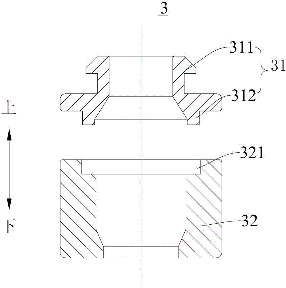
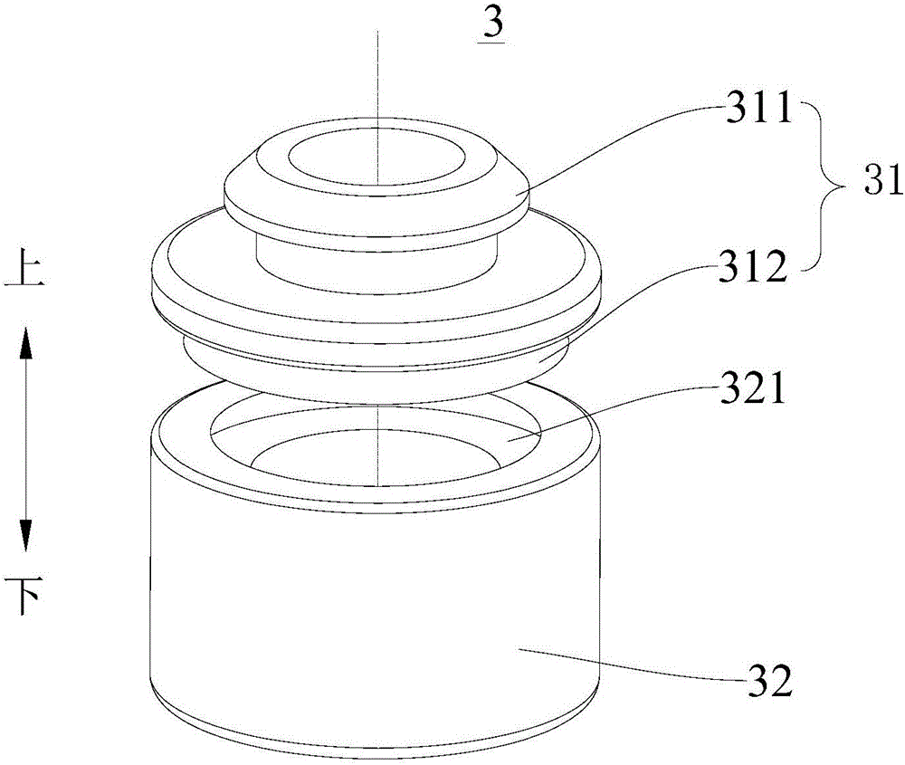
[0073] like Figure 3 to Figure 4 As shown, in this embodiment, the supporting portion 32 is formed into a column shape, the first matching portion is arranged on the upper end of the supporting portion 32 and is formed as a slot 321 with an open upper end, and the second matching portion is formed as a plug corresponding to the shape of the slot 321. The post 312 is detachably plugged into the slot 321 . Wherein, the radial dimension of the lower end of the slot 321 is greater than the radial dimension of the upper end, the radial dimension of the lower end of the insertion post 312 is greater than the radial dimension of the upper end, and the radial dimension of the slot 321 and the insertion post 312 is from the top Gradually increasing downwards, the insertion column 312 is snapped connected with the slot 321 .
[0074] That is to say, the outer diameter of the bottom end of the insertion post 312 is larger, and the outer diameter of the top of the insertion post 312 is ...
Embodiment 3
[0077] like Figure 5 to Figure 6As shown, in this embodiment, the supporting portion 32 is formed into a column shape, the first matching portion is arranged on the upper end of the supporting portion 32 and is formed as a slot 321 with an open upper end, and the second matching portion is formed as a plug corresponding to the shape of the slot 321. The post 312 is detachably plugged into the slot 321 .
[0078] Wherein, the slot 321 includes a first slot section 3211 and a second slot section 3212, the first slot section 3211 is located above the second slot section 3212, and the radial dimension of the first slot section 3211 is smaller than the radial dimension of the second slot section 3212 , The lower end of the insertion column 312 is provided with a buckle 313 whose radial dimension is larger than that of the upper end, and the buckle 313 is inserted into the second slot section 3212 .
[0079] Specifically, a buckle 313 is provided at the bottom of the insertion pos...
PUM
 Abstract
Description
Claims
Application Information
 - R&D Engineer
- R&D Manager
- IP Professional
- Industry Leading Data Capabilities
- Powerful AI technology
- Patent DNA Extraction
Browse by: Latest US Patents, China's latest patents, Technical Efficacy Thesaurus, Application Domain, Technology Topic, Popular Technical Reports.
© 2024 PatSnap. All rights reserved.Legal|Privacy policy|Modern Slavery Act Transparency Statement|Sitemap|About US| Contact US: help@patsnap.com