Crane with curve motion function

A crane and curve technology, which is applied in the directions of traveling mechanism, transportation and packaging, load hanging components, etc., can solve the problems of high cost, complex structure of wheel set consumables, and difficulty in running track to meet the operation of gantry cranes, and achieves a simple structure. Effect

Inactive Publication Date: 2016-09-21
崔会斌
View PDF6 Cites 0 Cited by
  • Summary
  • Abstract
  • Description
  • Claims
  • Application Information

AI Technical Summary

Problems solved by technology

[0002] Under normal circumstances, rail-operated cranes run along straight-line laying tracks. Due to the limitations of the natural conditions of the installation site or the needs of actual operations, sometimes they also run on curved tracks, such as the gantry cranes used in hydropower stations. Obviously, the existing running track is difficult to meet the operation of the gantry crane
[0003] Chinese patent CN104108650A discloses a curved running mechanism of a gantry crane, which includes a traveling trolley frame, and a lower rotating flange that matches the upper rotating flange at the bottom of the lower beam of the crane is installed on the traveling trolley frame. Large and small wheel sets, one side of the traveling trolley frame is equipped with a large wheel set that moves along the outer track of the curve, and the other side of the walking trolley frame is installed with a small wheel set that moves along the inner track of the curve. The two sides of the frame are respectively equipped with a plurality of flat stop wheels. When the crane enters the curved track from a straight line, the arc lengths of the inner diameter and outer diameter of the curved track are different. The large wheel set and the small wheel set correspond to the inner diameter and outer diameter of the curved track respectively The disadvantage of outer diameter walking is that the wheel set consumables of this operating mechanism have a complex structure, heavy weight, and high cost

Method used


Image

  • Crane with curve motion function
  • Crane with curve motion function
  • Crane with curve motion function

Examples


Embodiment Construction

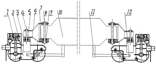
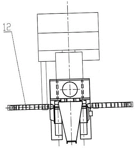
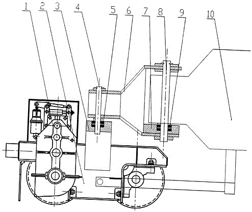
[0009] An embodiment of a crane capable of curve operation in the present invention is as follows: Figure 1-5 As shown, the cart running mechanism 1 is mounted on the trolley 2 for walking of the cart. The cart running mechanism is the same as the traditional cart running mechanism, and is also composed of a motor, a brake wheel coupling, a brake, Composed of reducer and wheels, the wheels are double rims, and the specific connection structure will not be described in detail.

[0010] The upper middle part of the trolley 2 is equipped with a trolley pressure bearing chamber 3, and a pressure bearing 5 is housed therein. Further, a trolley pressure bearing chamber 3 is respectively arranged in the middle of each wheel group and fixed on the on the trolley,

[0011] The two ends of the ground beam are respectively connected with a rocking arm 6, and the rocking arm 6 is as Figure 4 As shown, the diameter of the head end 6-1 of the rocker arm 6 is small, and the opening diame...


PUM


Abstract

The invention discloses a crane with a curve motion function. The crane comprises trolleys. Trolley pressure bearing chambers are mounted on the upper portions of the middles of the trolleys and are internally provided with pressure bearings. Rocker arms are connected to the two ends of a ground beam correspondingly. The head end of each rocker arm is small in diameter, and the tail end of each rocker arm is large in opening diameter. Holes formed in the head ends of the rocker arms in the perpendicular direction and trolley pressure bearing holes are concentric, connected through trolley vertical shafts correspondingly and fixed through clamp boards. Holes are formed in the tail ends of the rocker arms in the perpendicular direction; rocker arm bearing chambers are assembled in the lower holes and internally provided with rocker arm pressure bearings correspondingly; and rocker arm vertical shafts penetrate through the upper holes of the rocker arms and fall into the rocker arm bearing chambers correspondingly, and the holes formed in the tail ends of the rocker arms are connected through the rocker arm vertical shafts correspondingly. Tension spring support rods are mounted on the lower portion of the ground beam, and the other ends of the tension spring support rods are located on the lower portions of the trolleys correspondingly and connected with the trolleys through tension springs. The trolley pressure bearing chambers are fixed to the trolleys correspondingly through screws. The crane not only can move along straight lines, but also can meet the requirement for curve motion due to limitations of installation sites and natural conditions.

Description

Technical field: [0001] The invention relates to a crane capable of running through curves. Background technique: [0002] Under normal circumstances, rail-operated cranes run along straight-line laying tracks. Due to the limitations of the natural conditions of the installation site or the needs of actual operations, sometimes they also run on curved tracks, such as the gantry cranes used in hydropower stations. Obviously the existing running track is difficult to meet the operation of the gantry crane. [0003] Chinese patent CN104108650A discloses a curved running mechanism of a gantry crane, which includes a traveling trolley frame, and a lower rotating flange that matches the upper rotating flange at the bottom of the lower beam of the crane is installed on the traveling trolley frame. Large and small wheel sets, one side of the traveling trolley frame is equipped with a large wheel set that moves along the outer track of the curve, and the other side of the walking tr...

Claims


Application Information

Patent Timeline
Patent Type & Authority Applications(China)
IPC IPC(8): B66C9/04
CPCB66C9/04
Inventor 崔会斌
Owner 崔会斌
Why Eureka
Try Eureka