
A kind of manufacturing method of drawing mold of aircraft parts of resin-based composite material

A drawing mold and composite material technology, applied in the field of mold manufacturing, can solve the problems of limited number of manufacturing parts, difficult mold manufacturing, scratches on the surface of parts, etc., to increase part production capacity, improve mold utilization, and uniform hardness. Effect

Active Publication Date: 2018-06-29
SHENYANG CHINA AVIATION MERITT IND CO LTD
View PDF6 Cites 0 Cited by
  • Summary
  • Abstract
  • Description
  • Claims
  • Application Information

AI Technical Summary

Problems solved by technology

When working, the mold is installed on the stretching machine, and then the blank is clamped, and the stretching machine is started, so that the blank is close to the forming surface of the mold and gradually stretched to the designated position by tension to complete the forming of the part, but it has the following defects: First, The number of manufactured parts is limited. The reason is that after several times of work, due to the influence of friction between the mold surface and the blank, residues will be generated and remain on the mold surface, which is extremely difficult to clean, causing scratches or even scratches on the surface of the parts, resulting in The parts are scrapped; secondly, it is difficult to manufacture the mold because there must be no defects on the forming surface of the mold, such as air holes, sand holes, machining tool marks, etc. Once found, the whole set of molds may be scrapped; in addition, the mold is difficult to store, and must not be rusted during storage. Bumping is absolutely prohibited on the surface, and mold surface defects are found, which cannot be repaired. In addition, the quality is poor, and large parts often reach dozens of tons, which is very unfavorable for handling

Method used


Image

  • A kind of manufacturing method of drawing mold of aircraft parts of resin-based composite material
  • A kind of manufacturing method of drawing mold of aircraft parts of resin-based composite material
  • A kind of manufacturing method of drawing mold of aircraft parts of resin-based composite material

Examples


Embodiment Construction

[0023] In order to make the object, technical solution and advantages of the present invention clearer, the present invention will be further described in detail below in conjunction with the accompanying drawings and embodiments. It should be understood that the specific embodiments described here are only used to explain the present invention, not to limit the present invention.

[0024] A method for manufacturing a resin-based composite aircraft part drawing die, the specific steps of which are as follows:

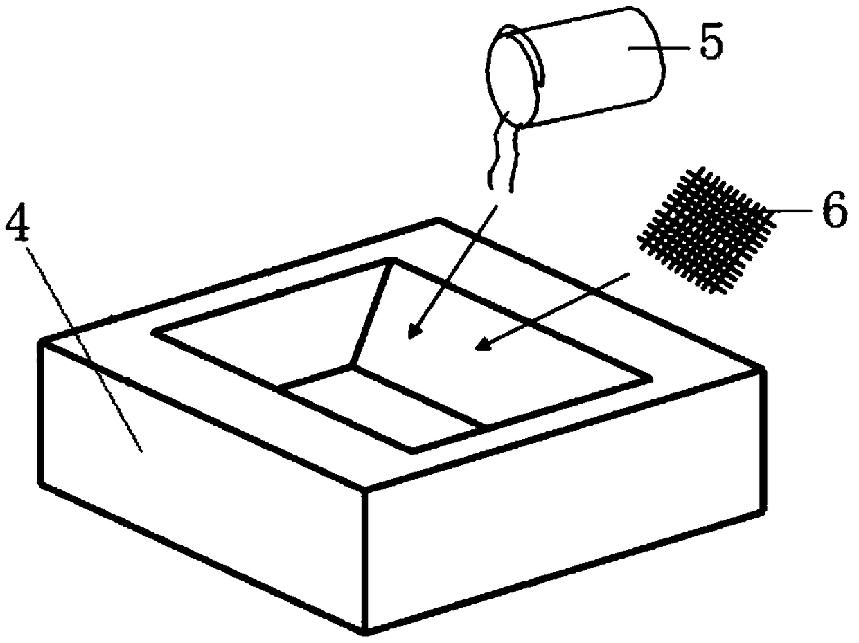
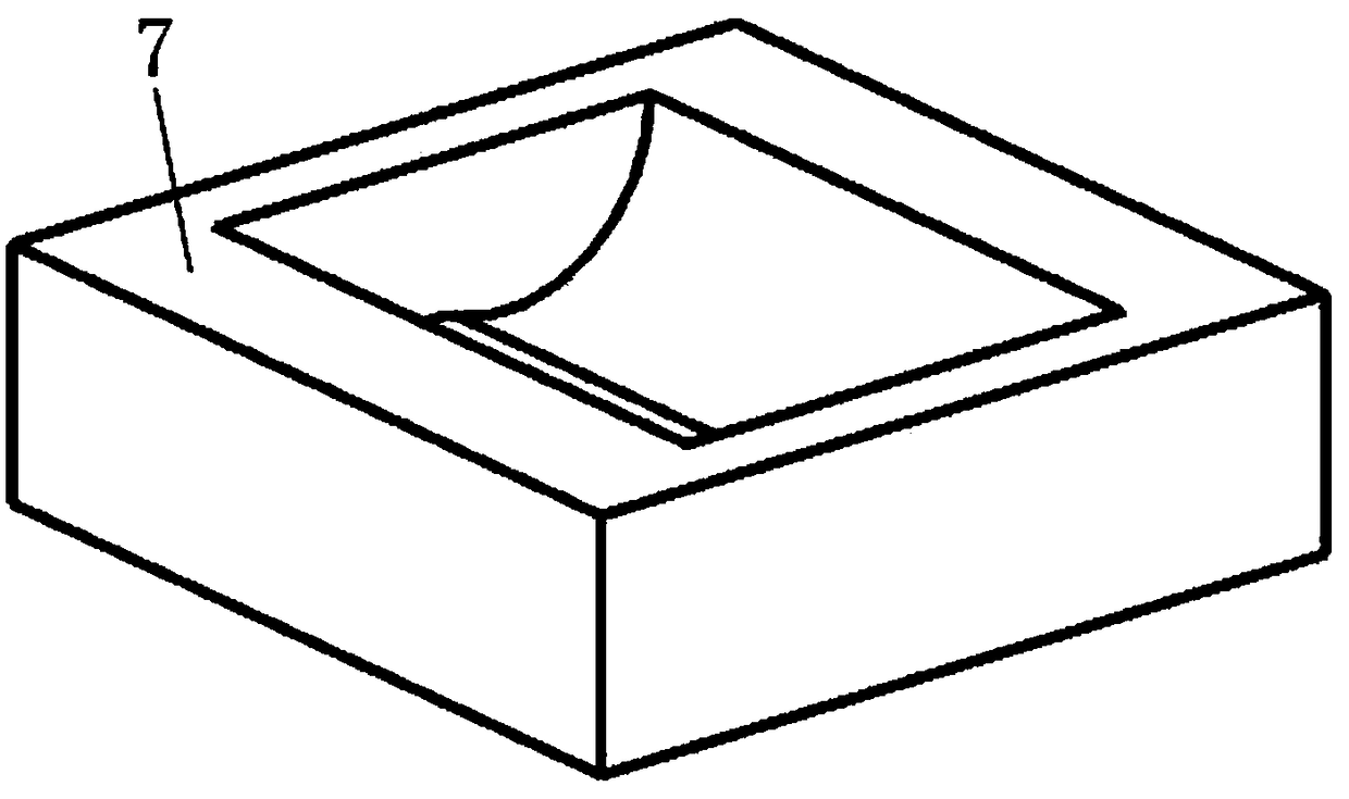
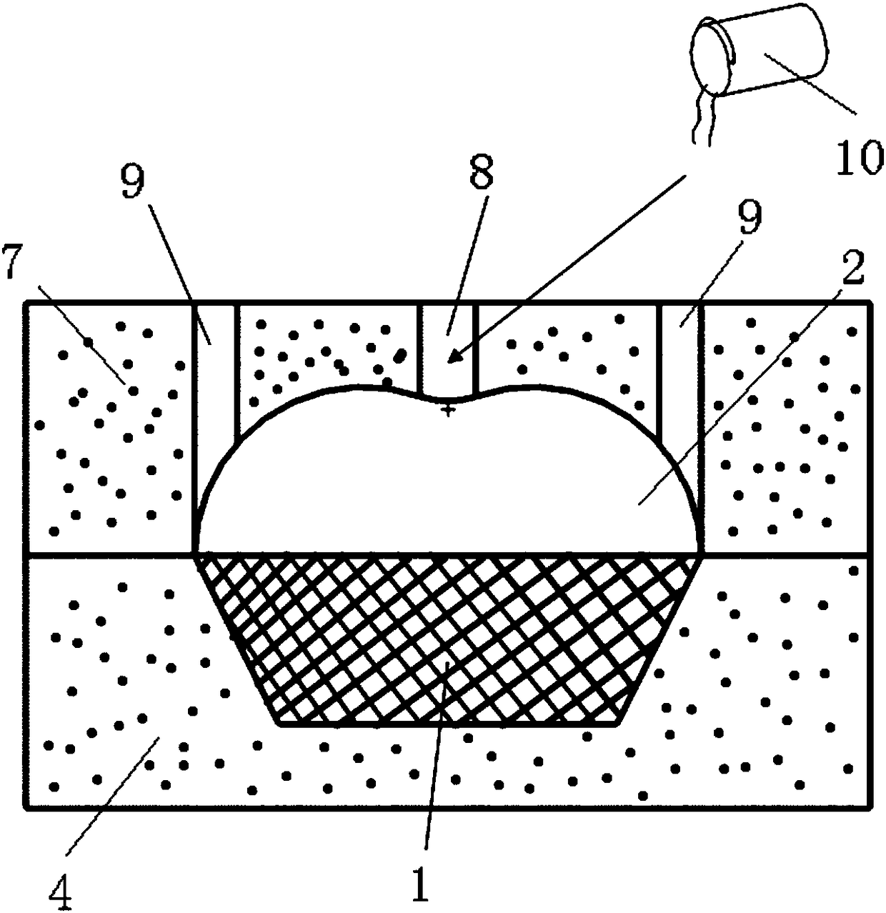
[0025] a. Refer to figure 1 , take the shape of the matrix 1 as the body core to make the foam matrix model 4, mix the epoxy-based resin material SAM910 and aluminum hydroxide powder into a muddy mixture 5 with a mass ratio of 100:400, and then mix the muddy mixture 5 Paste along the inner wall of the cavity of the foam matrix model 4. When the thickness reaches 50 mm, paste a layer of glass fiber cloth 6, repeat the above steps until the cavity of the foam matrix mode...


PUM


Abstract

The invention discloses a manufacturing method for an airplane part stretch-forming mold made of a resin matrix composite and mainly aims to solve the problems that existing molds are large in manufacturing difficulty, hard to store and large in weight and cannot be repaired. The provided manufacturing method for the airplane part stretch-forming mold made of the resin matrix composite comprises the steps that a matrix and a surface are manufactured with the resin matrix composite; and then the airplane part stretch-forming mold is machined and manufactured through a numerical control machine tool. By means of the manufacturing method, the mold using rate is increased, especially, the part productivity is improved, the mold manufacturing cost is reduced, and the mold manufacturing period is shortened.

Description

technical field [0001] The invention relates to a method for manufacturing a drawing die of a resin-based composite material aircraft part, and belongs to the field of die manufacturing. Background technique [0002] Aircraft parts drawing die is one of the key equipment for manufacturing aircraft parts. At present, most of them are made of steel and aluminum. According to the three-dimensional mathematical model designed by the mold, the casting blank made of steel or aluminum is processed on the CNC machine tool. When working, the mold is installed on the stretching machine, and then the blank is clamped, and the stretching machine is started, so that the blank is close to the forming surface of the mold and gradually stretched to the designated position by tension to complete the forming of the part, but it has the following defects: First, The number of manufactured parts is limited. The reason is that after several times of work, due to the influence of friction betwe...

Claims


Application Information

Patent Timeline
Patent Type & Authority Patents(China)
IPC IPC(8): B21D37/20B21D37/01B21D37/18
CPCB21D37/01B21D37/18B21D37/20
Inventor 万立新万立峰赵思程王义华
Owner SHENYANG CHINA AVIATION MERITT IND CO LTD
Learn More