


Quick Research
Generate reliable direction feasibility study reports for your R&D in just a few steps.

Technical Q&A
Discover and master advanced knowledge NOW. Basics, ideas, possibilities, all at once.

Find Solutions
As an expert in R&D theories, this can generate solutions to your technical problems instantly.

Evaluate Feasibility
Analyze your overall solution with one click, know your potential R&D risks in advance.

Monitor Landscape
Get weekly tech updates, stay abreast of the latest tech innovations and key insights.
Boiler
A boiler and steam tube technology, applied in the boiler field, can solve the problems of low energy utilization rate of fire tube boilers, easy fouling of water pipes, and unavailable water pipes, so as to improve energy utilization rate, avoid tube bursting, and improve combustion rate Effect
- Summary
- Abstract
- Description
- Claims
- Application Information
AI Technical Summary
Problems solved by technology
Method used
Image


Examples
Embodiment 1
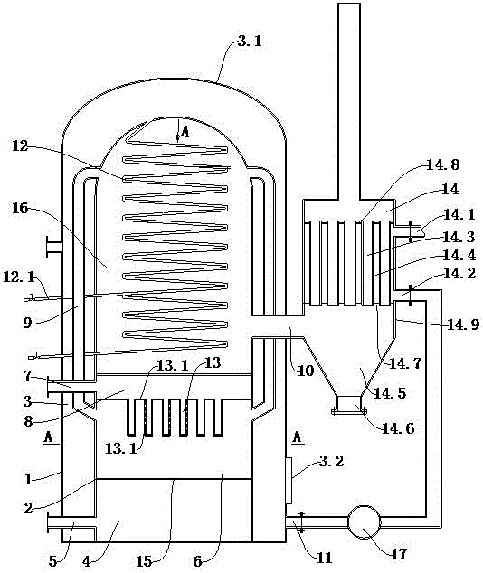
[0028] Embodiment 1: as figure 1 As shown, a steam boiler includes an outer wall 1 and an inner wall 2, the outer wall 1 and the inner wall 2 are closed to form a water storage chamber 3, the top of the water storage chamber 3 is a steam chamber 3.1, and the inside of the inner wall 2 From bottom to top, there are slag discharge chamber 4, combustion chamber 6, air chamber 8 and high temperature chamber 16; the air chamber 8 communicates with the upper air inlet 7, the slag discharge chamber 4 communicates with the lower air inlet 5, and the combustion chamber 6 is provided with a plurality of ventilation pipes 13 communicating with the air cavity 8, and a plurality of air nozzles 13.1 are arranged on the side wall of the ventilation pipe 13; the ventilation pipes 13 and the air nozzles 13.1 supply oxygen to the flame, so that The flammable gas is fully combusted.
[0029] A plurality of fire tubes 9 are evenly arranged in the water storage chamber 3, the bottom of the fire t...
Embodiment 2
[0033] Embodiment 2: as figure 1 As shown, a steam boiler includes an outer wall 1 and an inner wall 2, the outer wall 1 and the inner wall 2 are closed to form a water storage chamber 3, the top of the water storage chamber 3 is a steam chamber 3.1, and the inside of the inner wall 2 From bottom to top, there are slag discharge chamber 4, combustion chamber 6, air chamber 8 and high temperature chamber 16; the air chamber 8 communicates with the upper air inlet 7, the slag discharge chamber 4 communicates with the lower air inlet 5, and the combustion chamber 6 is provided with a plurality of ventilation pipes 13 communicating with the air chamber 8, and a plurality of air nozzles 13.1 are arranged on the side wall of the ventilation pipe 13; a plurality of fire pipes are uniformly arranged in the water storage chamber 3 9. The bottom of the fire pipe 9 communicates with the combustion chamber 6, the top of the fire pipe 9 communicates with the top of the high-temperature cha...
Embodiment 3
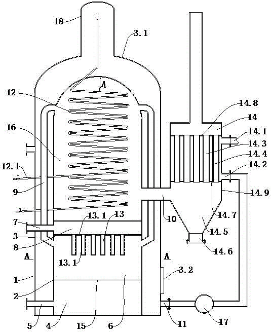
[0037] Embodiment 3: The difference between this embodiment and Embodiment 2 is that a steam chamber 18 is arranged on the top of the boiler in this embodiment, and the inner chamber cross-sectional area of the steam chamber 18 is smaller than the inner chamber cross-sectional area of the outer wall 1 of the boiler. Moreover, the upper end of the steam pipe 12 leads into the top of the steam chamber 18 . A safety valve can also be set at the steam chamber to further improve the safety factor of the boiler.
[0038] By adopting the above-mentioned technical scheme disclosed by the present invention, the following beneficial effects are obtained:
[0039] 1) The present invention arranges a plurality of fire tubes 9 between the outer wall 1 and the inner wall 2 of the boiler. After scaling on the outside of the fire tubes 9, the fire tubes 9 expand when heated, and the scale will automatically fall off, thereby effectively avoiding the generation of burst tubes .
[0040] ...
PUM
 Abstract
Description
Claims
Application Information
 - R&D Engineer
- R&D Manager
- IP Professional
- Industry Leading Data Capabilities
- Powerful AI technology
- Patent DNA Extraction
Browse by: Latest US Patents, China's latest patents, Technical Efficacy Thesaurus, Application Domain, Technology Topic, Popular Technical Reports.
© 2024 PatSnap. All rights reserved.Legal|Privacy policy|Modern Slavery Act Transparency Statement|Sitemap|About US| Contact US: help@patsnap.com