
High-cooling combined environment-friendly LED lamp

A LED lamp, combined technology, applied in the field of electron optics

Inactive Publication Date: 2016-09-07
魏国营
View PDF6 Cites 5 Cited by
  • Summary
  • Abstract
  • Description
  • Claims
  • Application Information

AI Technical Summary

Problems solved by technology

[0004] So far, there is no technical design that enables traditional lamps and lanterns to have the functions of repelling mosquitoes and releasing negative ions at the same time.

Method used


Image

  • High-cooling combined environment-friendly LED lamp
  • High-cooling combined environment-friendly LED lamp
  • High-cooling combined environment-friendly LED lamp

Examples


Embodiment 1

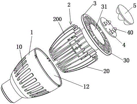
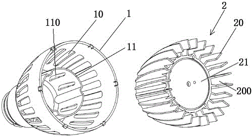
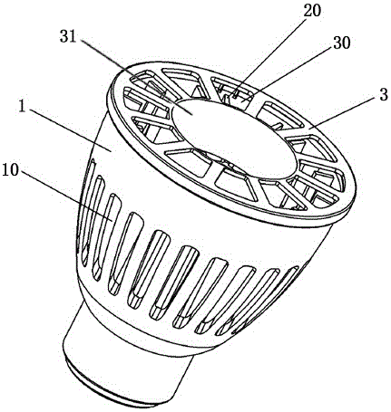
[0054] See Figure 1 to Figure 5 shown

[0055] A high heat dissipation combined environment-friendly LED lamp, including a heat dissipation housing 1, a power drive module (not shown in the figure), a heat dissipation assembly 2, an LED lighting assembly (not shown in the figure), a lens 5 and a fixing piece 3, the The side wall of the heat dissipation housing 1 is provided with a number of longitudinally arranged heat dissipation grooves 10, the heat dissipation grooves 10 run through the side wall of the heat dissipation housing 1, the heat dissipation assembly 2 has a hollow cavity and is used for arranging the The mounting panel 21 of the LED lighting assembly is provided with a number of longitudinally arranged heat dissipation fins 20 on the surface of the heat dissipation assembly 2, and a heat dissipation channel 200 is formed between every pair of adjacent heat dissipation fins 20, and the heat dissipation assembly 2 is closely spaced. Sleeved in the accommodation c...

Embodiment 2

[0081] A high heat dissipation combined environment-friendly LED lamp is characterized in that it includes a heat dissipation housing 1, a power drive module, a heat dissipation assembly 2, an LED lighting assembly, a lens 5 and a fixing part 3, and the side wall of the heat dissipation housing 1 is provided with several The heat dissipation groove 10 arranged vertically, the heat dissipation groove 10 runs through the side wall of the heat dissipation housing 1, the heat dissipation assembly 2 has a hollow cavity and a mounting panel 21 for arranging the LED lighting assembly. The surface of the heat dissipation assembly 2 is provided with a plurality of longitudinally arranged heat dissipation fins 20, and a heat dissipation channel 200 is formed between every pair of adjacent heat dissipation fins 20, and the heat dissipation assembly 2 is tightly sleeved on the heat dissipation housing 1. In the formed accommodating cavity 12, a hollow cylinder 11 for accommodating the powe...


PUM

PropertyMeasurementUnit
Particle sizeaaaaaaaaaa
Lengthaaaaaaaaaa
Particle sizeaaaaaaaaaa

Abstract

The invention discloses a high-cooling combined environment-friendly LED lamp. The high-cooling combined environment-friendly LED lamp comprises a cooling shell, a power driving module, a cooling assembly, an LED lighting assembly, a lens and a fixing piece. A plurality of longitudinally-formed cooling grooves penetrating through the side wall of the cooling shell are formed in the side wall of the cooling shell, the cooling assembly comprises a hollow cavity and an installation panel where the LED lighting assembly is installed, a plurality of longitudinally-arranged cooling fins are arranged on the surface of the cooling assembly, a cooling channel is formed between every two adjacent cooling fins, a plurality of longitudinally-formed cooling grooves are formed in the side wall of a hollow column, and the hollow column is coated with the hollow cavity of the cooling assembly; the portion between an aluminum-based PCB and the installation panel is evenly coated with a cooling coating. The high-cooling combined environment-friendly LED lamp has the effect of releasing negative ions, and has the effect of removing decoration pollutant including methanol, toluene, TVOC and the like to a certain degree, and the use functions of the lamp are enriched.

Description

technical field [0001] The invention relates to the field of electron optics, in particular to a high heat dissipation combined environment-friendly LED lamp. Background technique [0002] With the continuous change of human production technology, the functions of lamps, which are the necessities of people's life, are also changing with each passing day. At the same time, because people's concept of green environmental protection is getting stronger and stronger today, green and environmentally friendly lighting devices will be more favored by people. Therefore, In addition to traditional lighting functions, the pursuit of more humanized functions of lamps has become a development trend in today's lighting field. [0003] On the one hand, the negative air ion technology is applied to lamps and lanterns, so that the lamps can release air negative ions indoors for a long time, especially negative oxygen ions. Because it is similar in structure to superoxide anion radicals, it...

Claims


Application Information

Patent Timeline
IPC IPC(8): C08L91/00C08L63/02C08K13/04C08K7/14C08K5/00C08K3/04C08K5/3492C08K3/32C08K3/22C08K3/38C08K3/16F21V29/74F21V29/83F21Y115/10
CPCC08L91/00C08K2201/003C08K2201/004C08K2201/011C08L2203/20C08L2205/025C08L2205/035F21V29/74F21V29/83C08L63/00C08K13/04C08K7/14C08K5/0058C08K3/04C08K5/34922C08K2003/323C08K2003/2213C08K3/38C08K2003/162
Inventor 魏国营
Owner 魏国营
Learn More