
Cutting machine

A cutting machine and cutting knife technology, which is applied to sawing components, sawing equipment, circular saws, etc., can solve the problems that the plate is prone to shaking, affecting the accuracy of plate cutting, and position deviation.

Inactive Publication Date: 2016-09-07
ANHUI EMINENT BUILDING MATERIALS TECH
View PDF8 Cites 25 Cited by
  • Summary
  • Abstract
  • Description
  • Claims
  • Application Information

AI Technical Summary

Problems solved by technology

[0004] In view of the above-mentioned prior art, the object of the present invention is to overcome the cutting machine in the prior art, most of which directly push the plate manually and cut it with a cutting knife. Since the texture of the plate is relatively hard, the cutting knife is easy to cut the plate. Shaking occurs, prone to position shifting, affecting the accuracy of plate cutting, and the problem of low work efficiency of manual operation, so as to provide a method that can effectively fix the plate to be processed during use, so that the processing position is accurate, High cutting precision, can automatically cut the plate, cutting machine with high work efficiency

Method used


Image

  • Cutting machine

Examples


Embodiment Construction

[0025] Specific embodiments of the present invention will be described in detail below in conjunction with the accompanying drawings. It should be understood that the specific embodiments described here are only used to illustrate and explain the present invention, and are not intended to limit the present invention.

[0026] In the present invention, in the absence of a contrary description, the orientation words such as "upper, lower" and the like included in the term only represent the orientation of the term in the normal use state, or the common name understood by those skilled in the art, and should not be viewed as a limitation of this term.

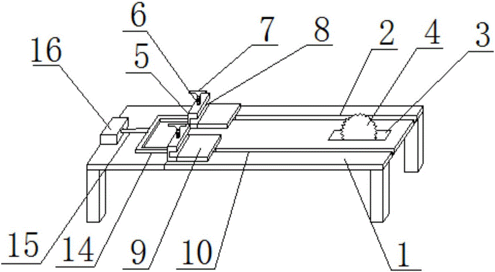
[0027] Such as figure 1 , the present invention provides a kind of cutting machine, described cutting machine comprises: workbench 1, cutting knife 4, clamping plate 5, threaded rod 6, driving mechanism, hydraulic pump 16, connecting rod 14 and telescopic rod 15, described The upper surface of the workbench 1 is recessed downwar...


PUM


Abstract

The invention discloses a cutting machine. The machine comprises a working platform, a cutter, clamping plates, threaded rods, a driving mechanism, a hydraulic pump, a connecting rod and a telescoping rod, wherein the upper surface of the working platform is downwards sunken to form a first chute and a second chute which are parallel to each other; the clamping plates are arranged on the first chute and the second chute; a cutter groove is arranged through the working platform, and the cutter is arranged in the cutter groove; clamping grooves are formed in the clamping plate; the threaded rods are arranged on the clamping plates; the hydraulic pump is arranged on the upper surface of the working platform; one end of the connecting rod is connected with one clamping plate while the other end of the connecting rod is connected with another clamping plate; one end of the telescoping rod is connected with the hydraulic pump while the other end of the telescoping rod is connected with the connecting rod. With the adoption of the cutting machine, the problems in the prior art that the deviation of a board in cutting leads to the failure of processing, and hard quality and easy-shaking property of the board influence the board cutting accuracy, and manual operation is low in working efficiency, can be solved.

Description

technical field [0001] The invention relates to the field of cutting machines. Background technique [0002] With the continuous development of modern wood products, the quality and precision requirements for wood cutting are also constantly improving. Most of the existing cutting machines use manual direct push of the board and cutting with a cutting knife. Hard, when the cutting knife is cutting, the plate is prone to shaking and position deviation, which affects the accuracy of plate cutting, and the work efficiency of manual operation is low. [0003] Therefore, it is an urgent problem to be solved by the present invention to provide a cutting machine that can effectively fix the plate to be processed during use so that the processing position is accurate, the cutting precision is high, the plate can be automatically cut, and the work efficiency is high. Contents of the invention [0004] In view of the above-mentioned prior art, the object of the present invention is...

Claims


Application Information

Patent Timeline
IPC IPC(8): B27B29/02B27B29/00B27B25/00B27B5/22
CPCB27B29/02B27B5/222B27B25/00B27B29/00
Inventor 万贤虎
Owner ANHUI EMINENT BUILDING MATERIALS TECH
Learn More