Automobile intake and exhaust flange and forging technology thereof

An air intake and exhaust and flange technology, which is applied in the field of mechanical forging, can solve the problems of insignificant improvement of material utilization rate, high production cost of cold plate, unstable edge density of products, etc. The effect of improving efficiency and improving utilization

Inactive Publication Date: 2016-09-07
常州市凯国机械制造有限公司
View PDF7 Cites 9 Cited by
  • Summary
  • Abstract
  • Description
  • Claims
  • Application Information

AI Technical Summary

Problems solved by technology

Because the shape of the automobile intake and exhaust flanges is irregular, the middle hole is large, waste waste is serious, and the utilization rate of materials is low, the production cost of the cold plate has been high, and the fracture surface of the product is not neat, not beautiful, and lacks industry competitiveness.
[0004] It is imperative for products in many fields to be realized by forging. More than 80% of the products in the industry will be realized by the open mold. The open mold is to put the raw materials into the mold cavity, squeeze out the waste edge, and then Cut off the waste edge to get the desired shape, so that the material utilization rate is not significantly improved, the edge density of the product is unstable, and the working environment is very poor, which is not a perfect forging production method

Method used


Image

  • Automobile intake and exhaust flange and forging technology thereof
  • Automobile intake and exhaust flange and forging technology thereof
  • Automobile intake and exhaust flange and forging technology thereof

Examples


Embodiment 1

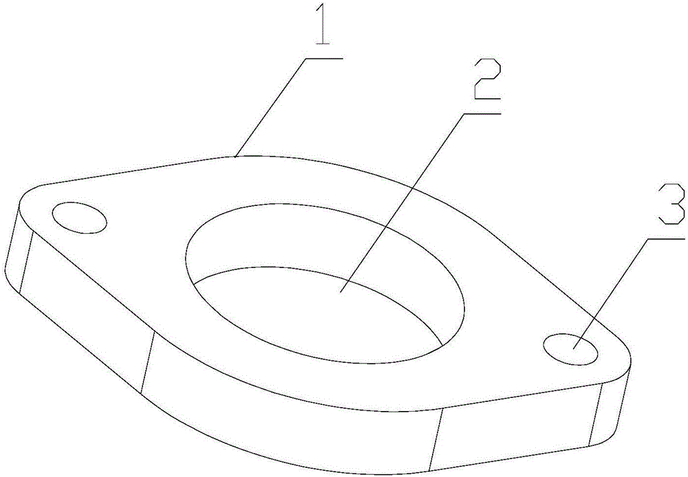
[0033] Such as figure 1 As shown, it is the automobile intake and exhaust flange of the present invention. The flange includes a main body 1 with a middle hole 2 and a mounting hole 3 at both ends of the middle hole 2 . The length of the mounting hole 3 and the aperture ratio of the mounting hole 3 are 1.3-1.5:1. In this embodiment, the thickness of the flange is 15 mm, the diameter of the mounting hole 3 is 11.5 mm, and the ratio of the length of the mounting hole 3 to the aperture It is 1.3, that is, the flange is a thick flange.

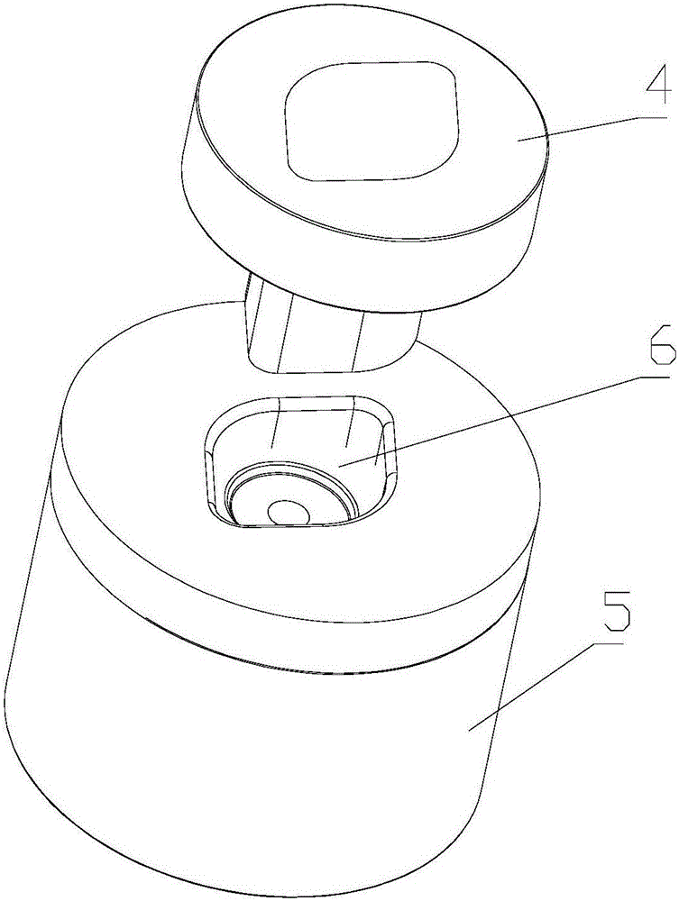
[0034] Such as figure 2 Shown, be the closed mold of the present invention, described closed mold comprises upper mold 4 and lower mold 5, and upper mold 4 and lower mold 5 surround and form molding cavity 6, and the shape of molding cavity 6 and described flange The shape fits.

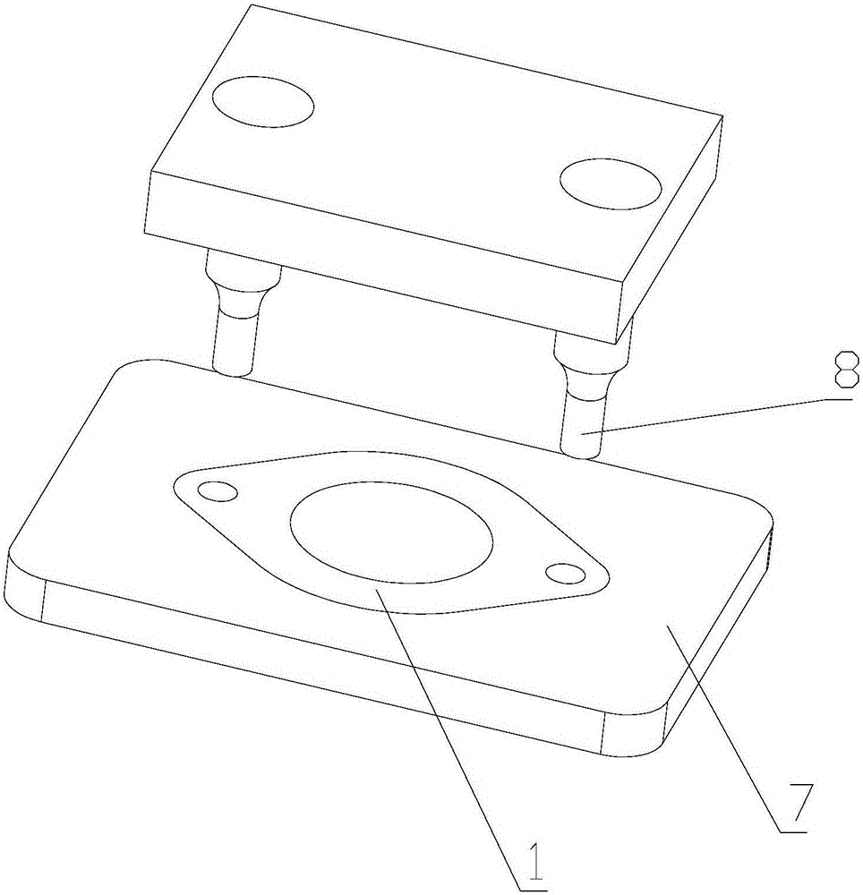
[0035] Such as image 3 Shown is the hydraulic press of the present invention, the hydraulic press includes a workbench 7 and a punch 8, the workbench 7 is provided...

Embodiment 2

[0049] In this embodiment, the structure of the flange, closed die and hydraulic press is the same as in Embodiment 1, the difference lies in the forging process of the flange, as follows:

[0050] A forging process for an automobile intake and exhaust flange, comprising the following steps:

[0051] (a) Cutting: Use a cutting machine or a band sawing machine to saw the rod-shaped raw material into a spare blank of the size required by the process;

[0052] (b) Heating: heat the billet through an intermediate frequency furnace for 4S, and the heating temperature is 1100°C;

[0053] (c) Pre-forging: the heated billet is flattened with a mold, the working pressure of the machine tool for flattening the billet is 70T, and the temperature of the flattened billet is 1200°C;

[0054] (d) Final forging: put the flattened blank into the closed die cavity for processing, and the final forging working pressure of the machine tool is 850T to obtain the blank;

[0055](e) punching the c...

Embodiment 3

[0060] In this embodiment, the structure of the flange, closed die and hydraulic press is the same as in Embodiment 1, the difference lies in the forging process of the flange, as follows:

[0061] A forging process for an automobile intake and exhaust flange, comprising the following steps:

[0062] (a) Cutting: Use a cutting machine or a band sawing machine to saw the rod-shaped raw material into a spare blank of the size required by the process;

[0063] (b) Heating: heat the billet through an intermediate frequency furnace for 7S, and the heating temperature is 1200°C;

[0064] (c) Pre-forging: flatten the heated billet with a mold, the working pressure of the machine tool to flatten the billet is 50T, and the temperature of the flattened billet out of the furnace is 1200°C;

[0065] (d) Final forging: put the flattened blank into the closed die cavity for processing, and the final forging working pressure of the machine tool is 750T to obtain the blank;

[0066] (e) pun...


PUM


Abstract

The invention relates to the technical field of mechanical forging, in particular to an automobile intake and exhaust flange and a forging technology thereof. The forging technology comprises the following steps that (a) blanking is conducted, specifically, a rod raw material is sawn into standby blanks with the dimension meeting the technological requirement through a blanking machine or a belt mill; (b) heating is conducted, specifically, the blanks are heated in an intermediate frequency furnace; (c) preforging is conducted, specifically, the heated blanks are pressed to be flat through a die; (d) finish forging is conducted, specifically, the flat blanks are put into a closed-type die cavity to be machined, and workblanks is obtained; (e) middle holesa are punched, specifically, the middle holes in the workblanks are cut off, and finished workblank flanges are obtained; (f) shot blasting is conducted, specifically, burrs on the surfaces of the workblank flanges are removed; (g) arrangement is conducted, specifically, the workblank flanges are arranged in sequence and transferred to a work surface of a hydraulic machine; and (h) an installation hole is punched, specifically, a suction cup sucks one flange and places the flange into a die of the hydraulic machine with a buffer device, and the installation hole (3) in the flange is punched. The technology greatly improves the quality of the flange, increases the utilization rate of the raw material, reduces the cost and enables the product to be more competitive.

Description

technical field [0001] The invention relates to the technical field of mechanical forging, in particular to an automobile intake and exhaust flange and a forging process thereof. Background technique [0002] All connecting parts that are closed at the same time by bolts on the periphery of the two planes are generally called "flanges". practicality. There are holes in the flange, and the installation can only be completed if there are holes, and the thin-walled flange can be realized by drilling and stamping. For thick-walled flanges, especially those whose punching thickness is much larger than the punching diameter, the efficiency of drilling with a drilling machine is low, the center distance often changes, and the accuracy cannot be guaranteed; when punching with a punching machine, the punch often breaks, the efficiency is low, and the waste is huge. . Therefore, it is particularly important how to achieve high efficiency under the condition that the punching accura...

Claims


Application Information

Patent Timeline
Patent Type & Authority Applications(China)
IPC IPC(8): B21J5/00B21J1/06B21J5/02F01N13/08F02M35/10
CPCB21J5/002B21J1/06B21J5/025F01N13/08F02M35/10091F02M35/1034
Inventor 郭雷
Owner 常州市凯国机械制造有限公司
Why Eureka
Try Eureka