
A perforated positioning grouting sleeve

A technology of grouting sleeves and positioning discs, which is applied to buildings, building reinforcements, building components, etc., can solve problems such as environmental pollution, inaccurate positioning, and easy tripping at joints, and achieve simple and efficient manufacturing processes. , the effect of a wide range of material sources

Inactive Publication Date: 2018-08-21
NANJING UNIV OF SCI & TECH
View PDF6 Cites 2 Cited by
  • Summary
  • Abstract
  • Description
  • Claims
  • Application Information

AI Technical Summary

Problems solved by technology

[0003] When lashing and lapping is used, the diameter range of the tying and lapping steel bars is limited, and the steel bars in the tension area are not suitable for use, and the steel bars at the lap joints are often too dense, and the amount of steel bars is increased.
[0004] When the welding method is used, although it generally does not have problems in terms of strength, stiffness, and destructive performance, it is highly affected by the worker's operating technology, the welding quality is unstable, the work efficiency is low, the power consumption is large, and there is a certain pollution to the environment. It is easily affected by the power supply on the construction site, and welding will also have defects such as undercut and incomplete penetration
[0005] Mechanical connection is divided into sleeve connection and threaded connection: threaded connection requires steel thread threading machine and torque wrench, resulting in that the steel bar section cannot reach the same strength, the joint is easy to trip, and the fracture quality is not easy to guarantee. At the same time, it is not suitable for joints with dense steel bars ; There are problems such as inaccurate positioning of the connection of the grouting sleeve, and the positioning plate hinders the grouting material, etc.

Method used


Image

  • A perforated positioning grouting sleeve
  • A perforated positioning grouting sleeve
  • A perforated positioning grouting sleeve

Examples


Embodiment Construction

[0021] The perforated positioning grouting sleeve of the present invention will be further described below.

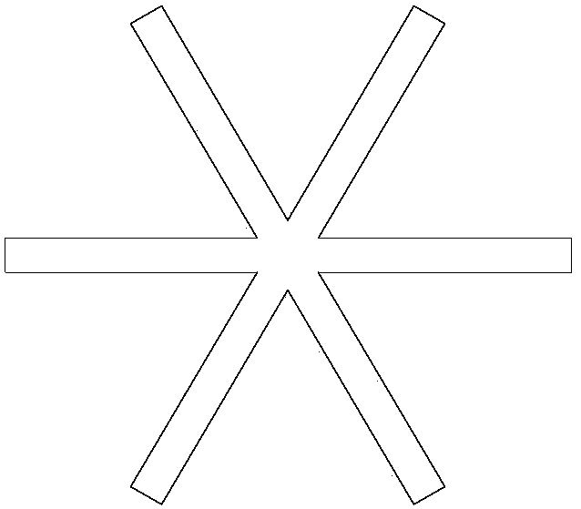
[0022] Perforated positioning grout sleeve, see figure 1 , including a seamless steel pipe 2 and a positioning plate 7; the inner wall of the seamless steel pipe 2 is lathe-processed to form a shear groove boss 6; Grouting holes 4 and grouting holes 5 are symmetrically arranged on the pipe wall at the end; a pair of positioning holes 8 are arranged in the middle of the seamless steel pipe 2 along the direction perpendicular to the length of the pipe as positioning points, so that the iron wire can penetrate into the positioning plate 7 to determine the connected position. The position of the steel bar 1; the positioning plate 7 and the seamless steel pipe 2 are set relatively independently.

[0023] Positioning plate 7, such as Figures 2 to 4 As shown, the shape is snowflake-shaped, and it is a snowflake-shaped positioning plate composed of three equidistant positio...


PUM


Abstract

The invention provides a perforation positioning grouting sleeve comprising a seamless steel pipe and a positioning disc; a shear groove boss is formed on the inner wall of the seamless steel pipe; openings at two ends of the seamless steel pipe are each provided with an elastic annular rubber ring, and a grouting hole and a slurry outlet hole are symmetrically arranged on the pipe wall close to the end parts of the seamless steel pipe respectively; a pair of positioning holes are formed in the middle part of the seamless steel pipe along the direction perpendicular to the pipe length direction; the positioning disc and the seamless steel pipe are relatively independently arranged. The sleeve adopts the positioning disc, can effectively control the position of reinforcing steel bars and makes the reinforcing steel bars not dislocated; the production process is simple and efficient, low in cost and reliable in performance, the length can be determined according to actual engineering requirements, the defects that a conventional sleeve has high cost and complex construction are greatly improved; the sleeve can be used for connection of the reinforcing steel bars between assembly type concrete structure precast components, and has broad application prospects.

Description

technical field [0001] The invention relates to a grouting sleeve for butt-joint connection of prefabricated and assembled concrete components with stressed reinforcement grout anchors, belonging to the technical field of construction engineering. Background technique [0002] With the development of the construction industry, especially the rapid development of high-rise buildings, steel bars have become the main support of building structures in construction engineering. At present, the steel bar connection technology can be divided into three categories, namely, steel bar binding lap joint, steel bar welding, and steel bar mechanical connection. [0003] When lashing and lapping is used, the diameter range of the tying and lapping steel bars is limited, and the steel bars in the tension area are not suitable for use, and the steel bars at the lap joints are often too dense, and the amount of steel bars is increased. [0004] When the welding method is used, although it g...

Claims


Application Information

Patent Timeline
Patent Type & Authority Patents(China)
IPC IPC(8): E04C5/16
CPCE04C5/165
Inventor 丁勇蔡武达张垠董雪花龚燚刘康康杨叶周凯迪张昊
Owner NANJING UNIV OF SCI & TECH
Learn More