An Adaptive Antistatic Enhanced Intelligent Power Module

An intelligent power module and adaptive circuit technology, which is applied to output power conversion devices, electrical components, etc., can solve problems such as overheating and burning, the intelligent power module 100 being vulnerable to static electricity threats, and fires.

Active Publication Date: 2019-06-07
SHENZHEN XIN YUPENG ELECTRONICS TECH CO LTD
View PDF6 Cites 0 Cited by
  • Summary
  • Abstract
  • Description
  • Claims
  • Application Information

AI Technical Summary

Problems solved by technology

[0050] It can be seen that the emitters of the IGBT tube 124, the IGBT tube 125, the IGBT tube 126, and the IGBT tube 127 of the current intelligent power module 100 are directly used as the pins of the intelligent power module 100. During the assembly process of the power module 100, the smart power module 100 is easily threatened by static electricity due to touching the operating table, touching the body parts of workers, etc. If these static electricity appear on the UN, VN, WN, -VP pins between the COM pin and the IGBT tube 124, the IGBT tube 125, the IGBT tube 126, and the IGBT tube 127. Therefore, the design of the current intelligent power module 100 has the defect of being damaged by static electricity during installation.
[0051] In fact, if this kind of damage makes the IGBT tube completely invalid, the detection after the assembly of the intelligent power module can be detected to avoid entering the market, but if the damage only causes slight damage to the IGBT tube, the detection after the assembly of the intelligent power module It will be difficult to be found, and entering the market will cause early failure of the product. IGBT tubes are power devices, and high voltage and high current flow through them. IGBT tubes are prone to overheating and burning at the moment of failure, causing the entire intelligent power module to burst. Heat accumulation may even cause the intelligent power module to explode, and in serious cases, fire and other safety accidents may occur

Method used


Image

  • An Adaptive Antistatic Enhanced Intelligent Power Module
  • An Adaptive Antistatic Enhanced Intelligent Power Module
  • An Adaptive Antistatic Enhanced Intelligent Power Module

Examples


Embodiment Construction

[0064] The present invention will be described in detail below in conjunction with the accompanying drawings and specific embodiments.

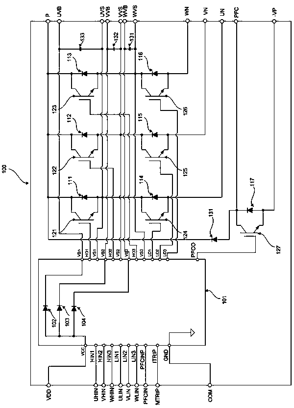
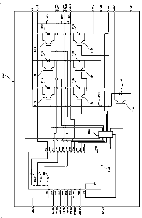
[0065] This embodiment provides an intelligent power module with self-adaptive antistatic enhancement. The structure diagram of the intelligent power module 1100 is as follows figure 2 shown. Wherein, the VCC terminal of the HVIC tube 1101 is used as the positive terminal VDD of the power supply in the low-voltage area of ​​the intelligent power module 1100, and VDD is generally 15V;

[0066] There is also a bootstrap circuit structure inside the HVIC tube 1101 as follows:

[0067] The VCC terminal is connected to the anodes of the bootstrap diode 1102, the bootstrap diode 1103, and the bootstrap diode 1104;

[0068] The cathode of the bootstrap diode 1102 is connected to the VB1 of the HVIC tube 1101;

[0069] The cathode of the bootstrap diode 1103 is connected to the VB2 of the HVIC tube 1101;

[0070] The cathode of the bootstrap dio...


PUM


Abstract

The invention discloses an adaptive antistatic property-enhanced intelligent power module. An HO1 end, an HO2 end, an HO3 end, an LO1 end, an LO2 end, an LO3 end and a PFCO end of an HVIC tube are connected with a first input end, a second input end, a third input end, a fourth input end, a fifth input end, a sixth input end and a seventh input end of an adaptive circuit respectively; a first output end, a second output end, a third output end, a fourth output end, a fifth output end, a sixth output end and a seventh output end of the adaptive circuit are connected with gates of various IGBT tubes respectively; and diodes which are connected with a power supply end and a GND end respectively are arranged in the adaptive circuit. When the adaptive antistatic property-enhanced intelligent power module is not powered on, the gates of the IGBT tubes have electric connection, so that direct voltage impacts on the gates are reduced; the antistatic capacity of the gates of the IGBT tubes is improved; and the probability that the intelligent power module is broken down by static electricity is reduced.

Description

technical field [0001] The invention relates to the design field of intelligent power modules, in particular to the design of a protection circuit and an electrostatic suppression circuit of an intelligent power module. Background technique [0002] Intelligent Power Module, or IPM (Intelligent Power Module), is a power drive product that combines power electronics and integrated circuit technology. The intelligent power module integrates the power switching device and the high-voltage driving circuit, and has built-in fault detection circuits such as overvoltage, overcurrent and overheating. On the one hand, the intelligent power module receives the control signal from the MCU to drive the subsequent circuit to work, and on the other hand, it sends the system status detection signal back to the MCU. Compared with traditional discrete solutions, intelligent power modules have won an increasing market due to their advantages of high integration and high reliability. They are...

Claims


Application Information

Patent Timeline
Patent Type & Authority Patents(China)
IPC IPC(8): H02M1/32
CPCH02M1/32
Inventor 尹曦曦
Owner SHENZHEN XIN YUPENG ELECTRONICS TECH CO LTD
Why Eureka
Try Eureka