
Graphical silicon-on-insulator substrate material and preparation method thereof

A technology of silicon-on-insulator and substrate materials, which is applied in semiconductor/solid-state device manufacturing, electric solid-state devices, semiconductor devices, etc. Scattering and other problems, to achieve the effect of simple structure and method, ensure material quality, and improve reliability

Active Publication Date: 2016-08-24
SHANGHAI INST OF MICROSYSTEM & INFORMATION TECH CHINESE ACAD OF SCI
View PDF4 Cites 13 Cited by
  • Summary
  • Abstract
  • Description
  • Claims
  • Application Information

AI Technical Summary

Problems solved by technology

[0008] First, there is a certain parasitic capacitance between the source drain and the substrate, which affects the device speed;
[0009] Second, the source-drain is coupled through the underlying BOX, which is prone to short-channel effects in smaller-sized devices;
[0010] Third, the defects in the insulating layer below the channel will scatter the channel carriers and affect the mobility of the carriers;
[0011] Fourth, after high-energy particles are incident, electron-hole pairs will be excited in the BOX insulating layer, which will affect the radiation resistance of the device
[0012] In addition, the existing substrate material manufacturing process often requires the introduction of separation technologies such as Smart-cut. Smart-cut requires annealing and peeling during the separation process. For SOI substrate materials with patterned cavity structures, the top silicon is vulnerable Local damage due to high stress

Method used


Image

  • Graphical silicon-on-insulator substrate material and preparation method thereof
  • Graphical silicon-on-insulator substrate material and preparation method thereof
  • Graphical silicon-on-insulator substrate material and preparation method thereof

Examples


Embodiment Construction

[0038] Embodiments of the present invention are described below through specific examples, and those skilled in the art can easily understand other advantages and effects of the present invention from the content disclosed in this specification. The present invention can also be implemented or applied through other different specific implementation modes, and various modifications or changes can be made to the details in this specification based on different viewpoints and applications without departing from the spirit of the present invention.

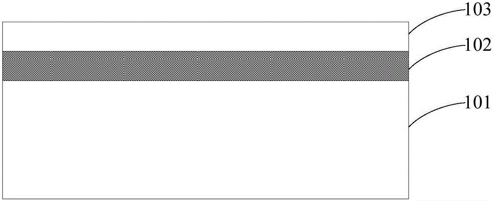
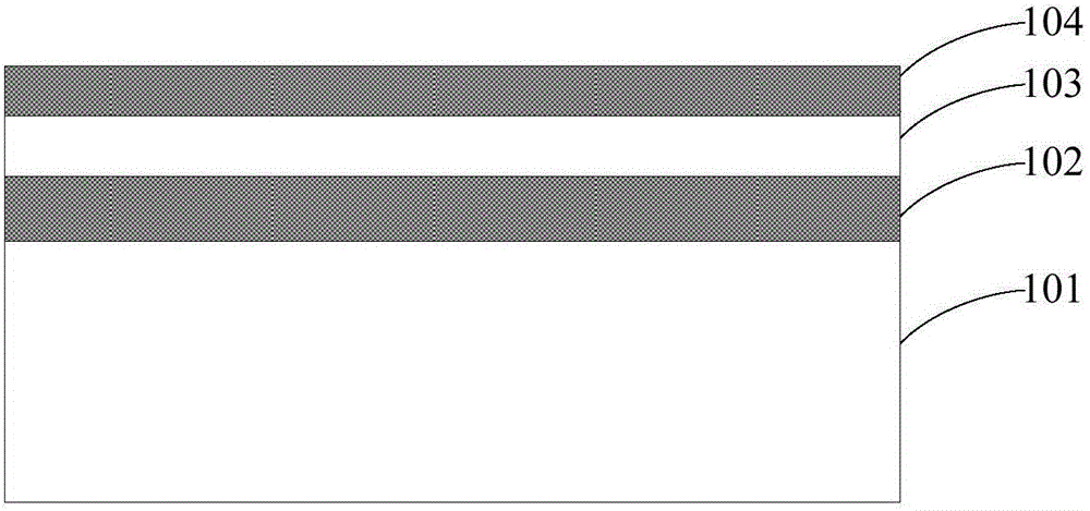
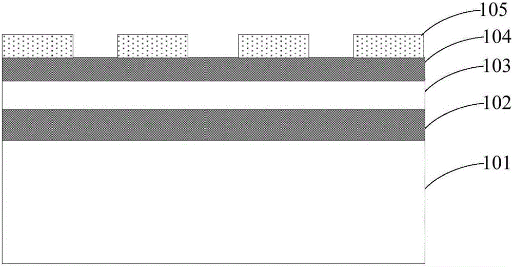
[0039] see Figure 1 to Figure 7 . It should be noted that the diagrams provided in this embodiment are only schematically illustrating the basic idea of ​​the present invention, so that only the components related to the present invention are shown in the diagrams rather than the number, shape and Dimensional drawing, the type, quantity and proportion of each component can be changed arbitrarily during actual implementation, and the ...


PUM

PropertyMeasurementUnit
Thicknessaaaaaaaaaa
Thicknessaaaaaaaaaa

Abstract

The invention provides a graphical silicon-on-insulator (SOI) substrate material and a preparation method thereof. The preparation method comprises the steps of 1) providing an SOI substrate comprising bottom silicon, a buried oxide layer and top silicon, and forming an insulating layer on the surface of the top silicon; 2) forming an etching window corresponding to a position for preparing a transistor channel; 3) etching the insulating layer to form a groove penetrating through the top silicon; 4) providing a silicon substrate, and bonding the silicon substrate and the insulating layer; 5) removing the bottom silicon; and 6) removing the buried oxide layer. The groove is formed in the insulating layer corresponding to the position for preparing the transistor channel, and the groove completely penetrates through the space between the top silicon and the bottom silicon, so that a hollowed area is formed below the transistor channel prepared later. In the substrate preparation process, annealing and peeling steps in a Smart-cut method are avoided while the quality of the material is guaranteed, so that the problem of breakage of the top silicon in the graphical area due to high stress is solved.

Description

technical field [0001] The invention relates to a semiconductor device substrate and a preparation method thereof, in particular to a patterned silicon-on-insulator substrate material and a preparation method thereof. Background technique [0002] SOI (Silicon-On-Insulator, silicon on insulating substrate) technology introduces a buried oxide layer between the top silicon and the back substrate. By forming a semiconductor thin film on an insulator, the SOI material has the incomparable advantages of bulk silicon: it can realize the dielectric isolation of components in integrated circuits, and completely eliminate the parasitic latch effect in bulk silicon CMOS circuits; The integrated circuit also has the advantages of small parasitic capacitance, high integration density, fast speed, simple process, small short channel effect, and is especially suitable for low-voltage and low-power circuits. Therefore, SOI has gradually become a deep submicron low-voltage, low-voltage Th...

Claims


Application Information

Patent Timeline
IPC IPC(8): H01L21/762H01L27/12
CPCH01L21/76243H01L27/1203
Inventor 俞文杰刘强刘畅文娇王翼泽王曦
Owner SHANGHAI INST OF MICROSYSTEM & INFORMATION TECH CHINESE ACAD OF SCI
Learn More