Coiled tubing drilling electric-hydraulic control directional tool

An electro-hydraulic control and coiled tubing technology, applied in directional drilling and other directions, can solve problems such as poor controllability, low efficiency, and poor precision, and achieve the effects of long service life, high locking efficiency, and easy control

Active Publication Date: 2016-08-24
BC P INC CHINA NAT PETROLEUM CORP +2
View PDF4 Cites 14 Cited by
  • Summary
  • Abstract
  • Description
  • Claims
  • Application Information

AI Technical Summary

Problems solved by technology

Although mechanical control and hydraulic directional tools are simple in structure, easy to operate, and low in cost, they have poor precision and poor controllability, and can only rotate the angle of the tool face in one direction, which is inefficient and is easily limited by the type of drilling fluid
The existing electro-hydraulic control directional tools can control the rotation of the tool face angle in two directions, and can complete complex coiled tubing directional drilling operations such as horizontal wells, sidetracked horizontal wells, and underbalanced drilling; The hydraulic action realizes the hydraulic locking tool face angle, the efficiency is relatively low, and the accuracy is relatively poor

Method used


Image

  • Coiled tubing drilling electric-hydraulic control directional tool
  • Coiled tubing drilling electric-hydraulic control directional tool
  • Coiled tubing drilling electric-hydraulic control directional tool

Examples


Embodiment Construction

[0047] In order to have a clearer understanding of the technical features, purposes and effects of the present invention, the specific implementation manners of the present invention will now be described with reference to the accompanying drawings.

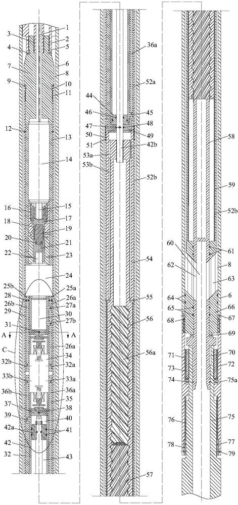
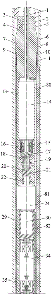
[0048] Such as figure 1 As shown, the present invention provides an electro-hydraulic control directional tool for coiled tubing drilling, which includes a driving member 14, a hydraulic pump 24, a reversing valve 34, a hydraulic cylinder 42, a driving shaft 56 and a mandrel 58 sequentially connected from top to bottom , the driving member 14 is used to drive the hydraulic pump 24, the driving member 4 is for example an electric motor, preferably a micro electric motor, the hydraulic pump 24 is used to pump hydraulic oil into the hydraulic cylinder 42 through the reversing valve 34, and the hydraulic pump 24 is relatively Preferably a miniature hydraulic pump;

[0049] Wherein, the hydraulic cylinder 42 includes a piston 42a, an...


PUM


Abstract

The invention provides a coiled tubing drilling electric-hydraulic control directional tool which comprises a driving part, a hydraulic pump, a reversing valve, a hydraulic cylinder, a drive shaft and a central spindle which are sequentially connected with one another from top to bottom, wherein the hydraulic cylinder comprises a piston, an upper cavity positioned above the piston, and a lower cavity positioned below the piston; the reversing valve is provided with an oil inlet communicated with the hydraulic pump, a first working hole communicated with the upper cavity, and a second working hole communicated with the lower cavity; one end of the drive shaft is connected with the piston; and the other end of the drive shaft can be rotationally connected with the central spindle. According to the invention, flow direction of hydraulic oil is controlled by virtue of the reversing valve, axial reciprocating motion or stop of the piston of the hydraulic cylinder is further controlled, bidirectional rotating or locking of the central spindle is controlled by virtue of the axial reciprocating motion or stop of the drive shaft, and translation is changed into rotation, so that bidirectional continuous control of rotation of a tool face angle can be realized, the tool face is locked by the reversing valve, the hydraulic locking efficiency is improved, and the controllability is high.

Description

technical field [0001] The invention relates to a downhole tool for coiled tubing drilling, in particular to an electro-hydraulic control directional tool for coiled tubing drilling. Background technique [0002] Coiled tubing drilling technology is one of the more advanced drilling technologies in the world at present. It has many technical advantages such as reducing drilling costs and saving drilling cycles. Therefore, this technology has been widely used abroad. In China, the research on coiled tubing drilling technology is just in its infancy. [0003] The coiled tubing drilling directional tool is the core tool in the coiled tubing drilling process. It controls the wellbore direction by adjusting the motor tool face, which determines the technical level of trajectory control in the coiled tubing drilling process. The development of directional tools has gone through several stages such as mechanical control, hydraulic control, electric control and electro-hydraulic co...

Claims


Application Information

Patent Timeline
IPC IPC(8): E21B7/04
CPCE21B7/04
Inventor 李猛贺会群熊革智勇蒲晓莉罗刚张士彬张云飞
Owner BC P INC CHINA NAT PETROLEUM CORP
Why Eureka
Try Eureka