Draught fan system and locking device thereof

A technology of locking device and fan system, which is applied to components, mechanical equipment, quick-action fasteners, etc. of pumping devices for elastic fluids, and can solve problems such as locking difficult objects, so as to improve efficiency and facilitate locking The effect of tightening and reducing difficulty

Active Publication Date: 2015-04-29
GREE ELECTRIC APPLIANCES INC
View PDF6 Cites 3 Cited by
  • Summary
  • Abstract
  • Description
  • Claims
  • Application Information

AI Technical Summary

Problems solved by technology

[0003] The present invention aims to provide a fan system and its locking device to solve the problem that it is difficult to lock objects in a narrow space in the prior art

Method used


Image

  • Draught fan system and locking device thereof
  • Draught fan system and locking device thereof
  • Draught fan system and locking device thereof

Examples


Embodiment Construction

[0023] The embodiments of the present invention will be described in detail below with reference to the accompanying drawings, but the present invention can be implemented in many different ways defined and covered by the claims.

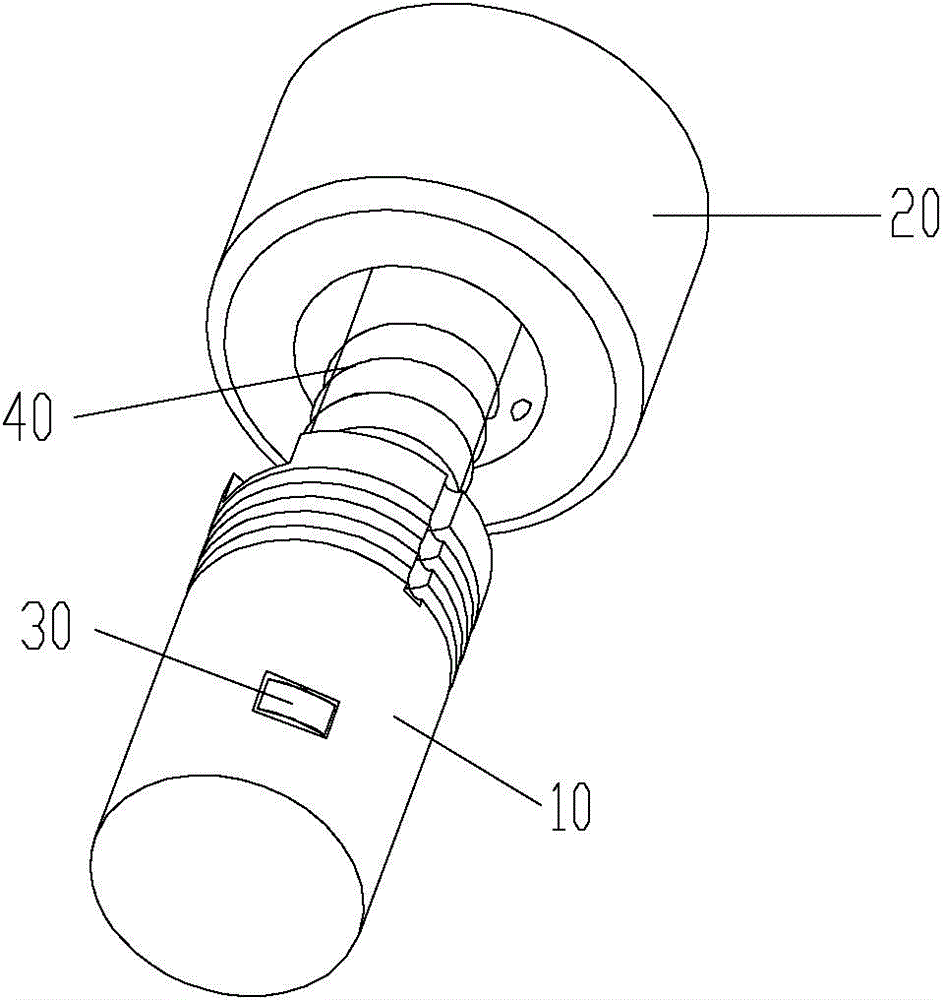
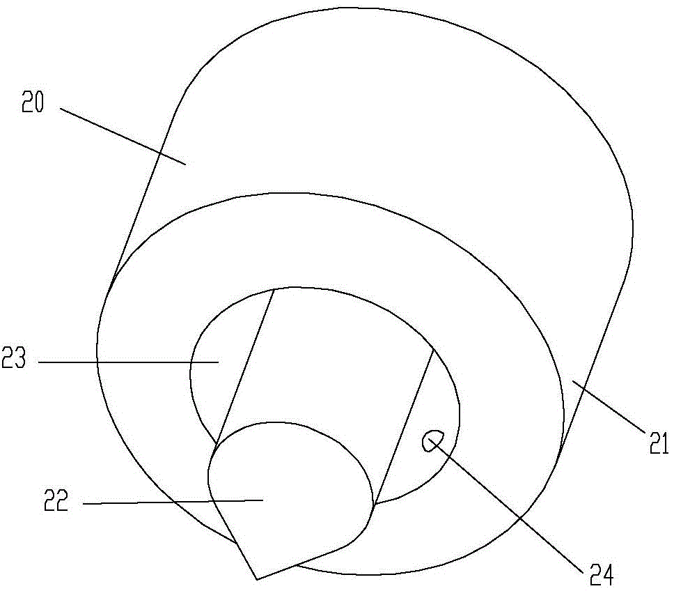
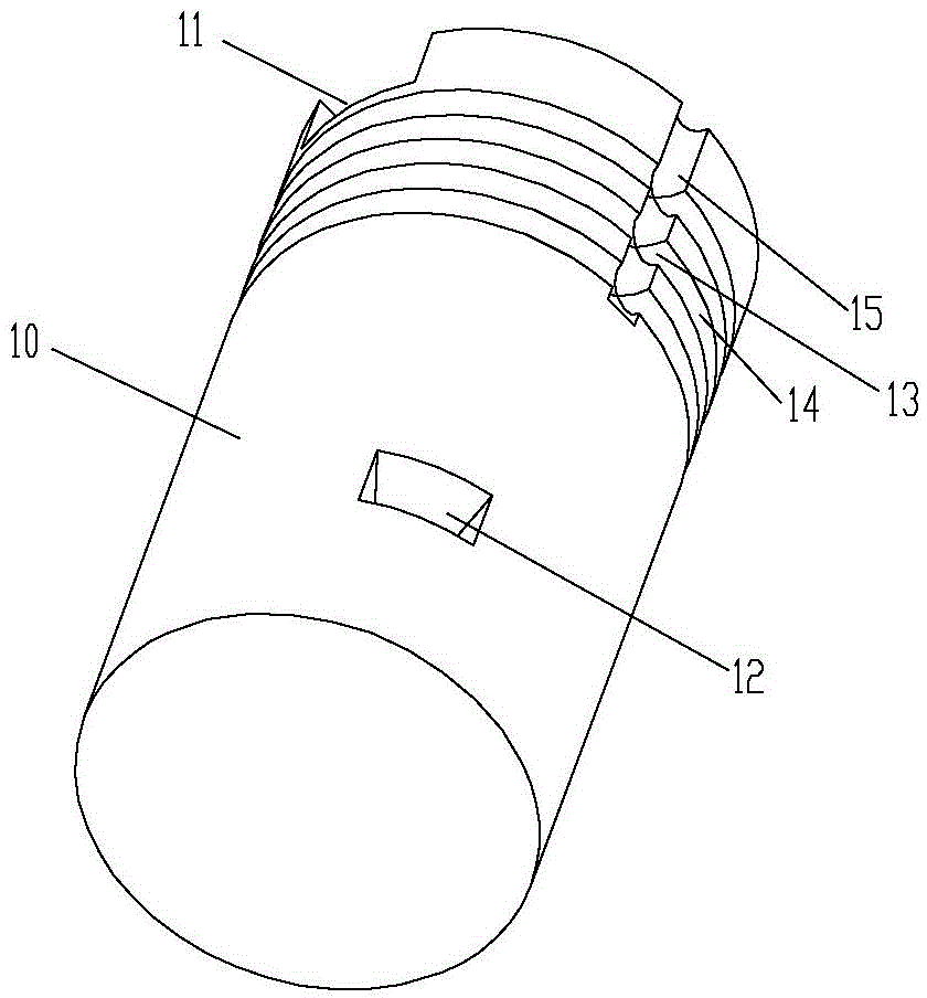
[0024] For an aspect of the invention, please refer to Figure 1 to Figure 4 , provides a locking device, including: a body 10, a housing cavity is arranged in the body 10, a hole 12 is opened on the side wall of the body 10; a locking member 30, the locking member 30 is movably arranged in the hole of the body 10 12; the operating part 20 is detachably locked and connected to the main body 10, and has an axial positioning structure with the main body 10, one end of the operating part 20 is inserted into the accommodating cavity, and the locking part 30 acts on one end of the operating part 20 It protrudes downward to the outside of the main body 10 .

[0025] combine Figure 1 to Figure 4 , when using the present invention for locking and positio...


PUM


Abstract

The invention provides a draught fan system and a locking device of the draught fan system. The locking device comprises a body, a locking piece and an operating piece, wherein the body is provided with a containing cavity, the side wall of the body is provided with a hole, the locking piece is flexibly arranged in the hole of the body, the operating piece is detachably connected with the body, an axial positioning structure is arranged between the operating piece and the body, one end of the operating piece is inserted into the containing cavity, and the locking piece extrudes from the outside of the body under the function of one end of the operating piece. The locking device has the advantages of being convenient to disassemble and install, is not limited by installation tools, can lock objects easily, and can greatly reduce the difficulty of locking when the objects are locked in a narrow and small space. Moreover, by adoption of the locking device, threads need not processing, so that the process of locking is reduced, the problem that thread holes are difficult to be processed in a narrow space is solved, and the locking efficiency is improved.

Description

technical field [0001] The invention relates to the field of positioning adjustment, and more specifically, to a fan system and a locking device thereof. Background technique [0002] In the prior art, screws are generally used to lock and position objects in a narrow space. However, due to the limitation of space and installation tools, the installation and removal of screws are usually difficult to achieve; in addition, positioning with screws sometimes requires machining It is very difficult to complete this process in a small space to produce threaded holes for screws to pass through. For example, when using screws to lock and position the motor shaft in the hub in the fan system, since the hub is located in a small space in the fan system, it will be difficult to install and remove the screws. At the same time, on the hub It is also difficult to process threaded holes for screws to pass through. Contents of the invention [0003] The present invention aims to provid...

Claims


Application Information

Patent Timeline
Patent Type & Authority Applications(China)
IPC IPC(8): F16B21/10F16B21/08F04D29/64
CPCF04D29/64F16B21/08
Inventor 王继承周军段向春周金冶张馨云马重夫
Owner GREE ELECTRIC APPLIANCES INC
Why Eureka
Try Eureka