
Mask plate, manufacturing method of display substrate, display substrate and display device

A technology for displaying substrates and manufacturing methods, which is applied to the photoplate-making process of patterned surfaces, originals for photomechanical processing, instruments, etc., and can solve problems such as poor geometric shape and mismeasurement of glass substrate edges

Active Publication Date: 2021-01-22
BOE TECH GRP CO LTD +1
View PDF10 Cites 0 Cited by
  • Summary
  • Abstract
  • Description
  • Claims
  • Application Information

AI Technical Summary

Problems solved by technology

[0005] The technical problem to be solved by the present invention is: how to solve the problem that in the existing array substrate manufacturing process, when measuring the center offset of the reference layer pattern, it is easy to cause serious mismeasurement due to poor geometric shape of the edge of the glass substrate

Method used


Image

  • Mask plate, manufacturing method of display substrate, display substrate and display device
  • Mask plate, manufacturing method of display substrate, display substrate and display device
  • Mask plate, manufacturing method of display substrate, display substrate and display device

Examples


Embodiment Construction

[0031]The specific embodiments of the present invention will be described in further detail below in conjunction with the drawings and embodiments. The following examples are used to illustrate the present invention, but not to limit the scope of the present invention.

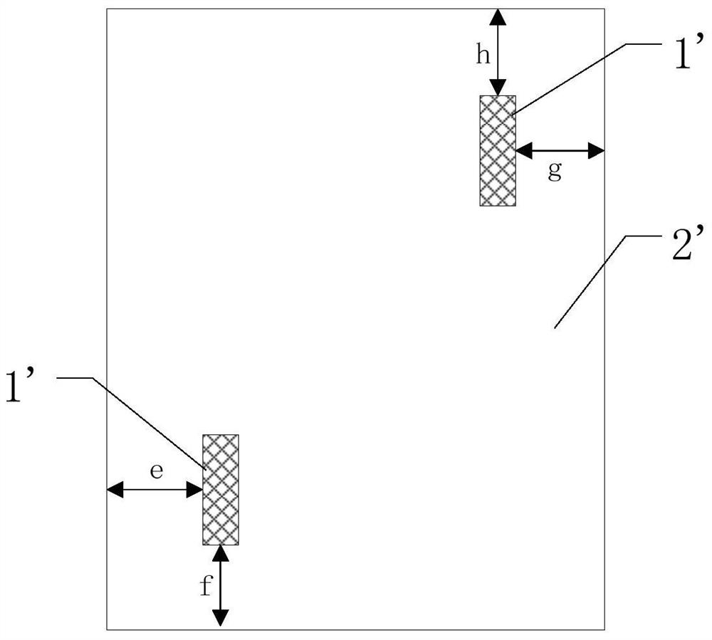
[0032]The embodiment of the present invention provides a mask, which includes a first mask pattern for making a display pattern on a base substrate, and also includes a second mask pattern, the second mask pattern being used for A marking pattern is made on the base substrate, and the marking pattern is used to determine the center offset of the display pattern relative to the base substrate.

[0033]In the mask provided by the embodiment of the present invention, by adding a second mask pattern, the mask can be used to make a display pattern on a base substrate (such as a glass substrate) while making a marking pattern on the base substrate. The mark pattern can determine the center offset of the display pattern relative...


PUM


Abstract

The invention provides a mask plate, a manufacturing method of a display substrate, the display substrate and a display device. The mask plate comprises a first mask pattern and a second mask pattern, wherein the first mask pattern is used for manufacturing a display pattern on a substrate body, the second mask pattern is used for manufacturing a marking pattern on the substrate body, and the marking pattern is used for determining the center offset, relative to the substrate body, of the display pattern. The mask plate has the advantages that by the second mask pattern, the marking pattern can be manufactured on the substrate body while the display pattern is manufactured on the substrate body, and the center offset, relative to the substrate body, of the display pattern can be determined by the marking pattern; the influence, caused by the bad geometrical shape of the edge of a glass substrate, on measuring results can be avoided as compared with an existing center offset measuring manner, and the center offset of each exposure region of the substrate body can be measured.

Description

Technical field[0001]The present invention relates to the field of display, in particular to a mask, a manufacturing method of a display substrate, a display substrate and a display device.Background technique[0002]Thin Film Transistor-Liquid Crystal Display (TFT-LCD) is a display device with a wide range of sizes, low energy consumption, and low radiation. In the photolithography (PHOTO) process of the TFT-LCD manufacturing process, When performing photolithography on the reference layer (usually the first layer structure on the glass substrate), it is necessary to confirm the center shift of the reference layer pattern (center shift, that is, the shift of the pattern center of the reference layer relative to the center of the glass substrate) The center offset has a great impact on the subsequent lithography alignment and the alignment of the array substrate (TFT substrate) and the color filter substrate (CF substrate). For a certain period of time, the center offset of the produc...

Claims


Application Information

Patent Timeline
Patent Type & Authority Patents(China)
IPC IPC(8): G03F1/84
CPCG03F1/84
Inventor 张玉虎金宇
Owner BOE TECH GRP CO LTD
Learn More