Machine vision lens and imaging method with large field of view and large aperture

A machine vision, large-aperture technology, used in instruments, optical components, optics, etc., can solve the problems of unable to meet the needs of high-end products, unable to meet the large field of view, large aperture, low distortion, high resolution, etc., and achieve low distortion. , to meet the needs of high-end products, the effect of large field of view

Active Publication Date: 2019-07-09
FUJIAN NORMAL UNIV
View PDF6 Cites 0 Cited by
  • Summary
  • Abstract
  • Description
  • Claims
  • Application Information

AI Technical Summary

Problems solved by technology

However, for the existing domestic machine vision lenses with large field of view and large aperture, they cannot meet the requirements of large field of view, large aperture, low distortion, and high resolution at the same time, and cannot meet the needs of high-end products.

Method used


Image

  • Machine vision lens and imaging method with large field of view and large aperture
  • Machine vision lens and imaging method with large field of view and large aperture
  • Machine vision lens and imaging method with large field of view and large aperture

Examples


Embodiment 1

[0039] In this embodiment, the optical system data is as follows:

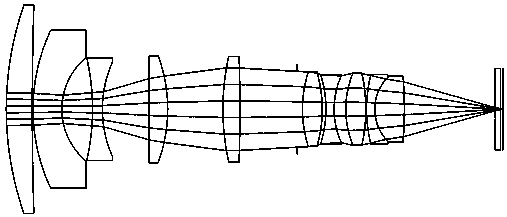
[0040] optical surface Radius (mm) Thickness (mm) Refractive index Abbe number 1 41.650 3.63 1.70 56.20 2 404.854 0.31 3 25.643 4.00 1.88 40.81 4 9.290 4.15 5 -32.362 1.10 1.85 30.06 6 15.304 6.48 7 1823.039 2.46 1.69 53.35 8 -21.825 7.57 9 31.052 2.15 1.92 20.88 10 -206.986 7.83 aperture Infinity 0.74 12 16.357 2.66 1.51 60.48 13 -16.391 1.10 1.76 27.55 14 10.569 1.71 15 12.625 2.67 1.69 49.23 16 -24.689 0.12 17 18.171 1.46 1.75 35.02 18 6.102 3.65 1.53 60.47 19 -81.242 12.91 Image surface Infinity

[0041] In this embodiment, the focal length of the optical system is 8.5 mm.

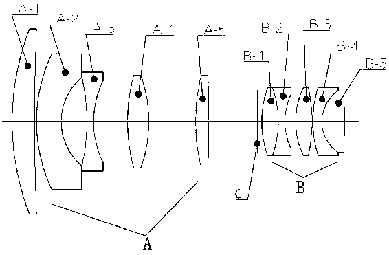
[0042] In this embodiment, lens A-4 is a biconvex lens.

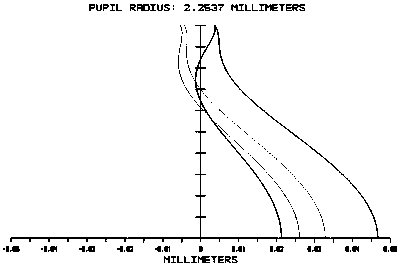
[0043] The focus data table is as follows:

[0044]

[0045] In this...

Embodiment 2

[0052] In this embodiment, the optical system data is as follows:

[0053] optical surface Radius (mm) Thickness (mm) Refractive index Abbe number 1 31.116 2.53 1.70 56.2 2 329.675 0.07 3 18.138 2.81 1.88 40.8 4 6.597 3.00 5 -22.319 0.96 1.85 30.1 6 11.430 4.57 7 Infinity 1.80 1.69 53.3 8 -15.085 5.39 9 23.858 1.66 1.92 20.9 10 -147.834 5.58 aperture Infinity 0.51 12 12.011 1.93 1.51 60.5 13 -12.926 0.36 14 -11.285 0.79 1.76 27.5 15 8.001 1.14 16 9.305 1.95 1.69 49.2 17 -16.114 0.07 18 13.815 0.79 1.75 35.0 19 4.470 2.89 1.53 60.5 20 -41.272 9.38 Image surface Infinity

[0054] In this embodiment, the focal length of the optical system is 6 mm.

[0055] In this embodiment, lens A-4 is a plano-convex lens.

[0056] The focus data table is as follows:

[0057] ...


PUM


Abstract

The invention relates to a machine vision lens with the large visual field and the large aperture and an imaging method. The machine vision lens comprises an optical system arranged in a lens cone. The optical system comprises a front set A with the positive focal power, a variable diaphragm C and a back set B with the positive focal power, wherein the front set A with the positive focal power, the variable diaphragm C and the back set B with the positive focal power are sequentially arranged in the light incident direction. The front set A comprises a positive meniscus lens A-1, a negative meniscus lens A-2, a biconcave lens A-3, a lens A-4 and a biconvex lens A-5, wherein the positive meniscus lens A-1, the negative meniscus lens A-2, the biconcave lens A-3, the lens A-4 and the biconvex lens A-5 are sequentially arranged. The back set B is a gluing set, and comprises a biconvex lens B-1, a biconcave lens B-2, a biconvex lens B-3, a negative meniscus lens B-4 and a biconvex lens B-5, wherein the biconvex lens B-1, the biconcave lens B-2, the biconvex lens B-3, the negative meniscus lens B-4 and the biconvex lens B-5 are sequentially arranged and closely connected. The machine vision lens has the advantages of being large in visual field angle, low in distortion, large in relative aperture, high in resolution and short in total optical length, and the requirement of a high-end product is met.

Description

technical field [0001] The invention relates to the technical field of machine vision lenses, in particular to a machine vision lens with a large field of view and large aperture and an imaging method. Background technique [0002] Machine vision is a machine that replaces the human eye for measurement and judgment. The machine vision system refers to converting the ingested target into an image signal through a machine vision product (that is, an image capture device, which is divided into two types: CCD and CMOS), and sending it to a dedicated image processing system. The image system performs various calculations on these signals to extract the characteristics of the target, and then controls the on-site equipment actions according to the results of the discrimination. In recent years, with the rapid development of the microelectronics industry, machine vision systems with high resolution and high processing speed have been born continuously, which puts forward new requi...

Claims


Application Information

Patent Timeline
Patent Type & Authority Patents(China)
IPC IPC(8): G02B13/00
CPCG02B13/0015
Inventor 林峰曾振煌
Owner FUJIAN NORMAL UNIV
Why Eureka
Try Eureka