A kind of self-adaptive tuning vibration table and detection method
A detection method and vibration table technology, which is applied in the field of instrument detection, can solve the problems that the vibration effect cannot be monitored in real time, and the vibration frequency adaptive control of the instrument vibration table cannot be controlled, so as to achieve the effect of real-time monitoring of the vibration effect
- Summary
- Abstract
- Description
- Claims
- Application Information
AI Technical Summary
Problems solved by technology
Method used
Image
Examples
specific Embodiment approach 1
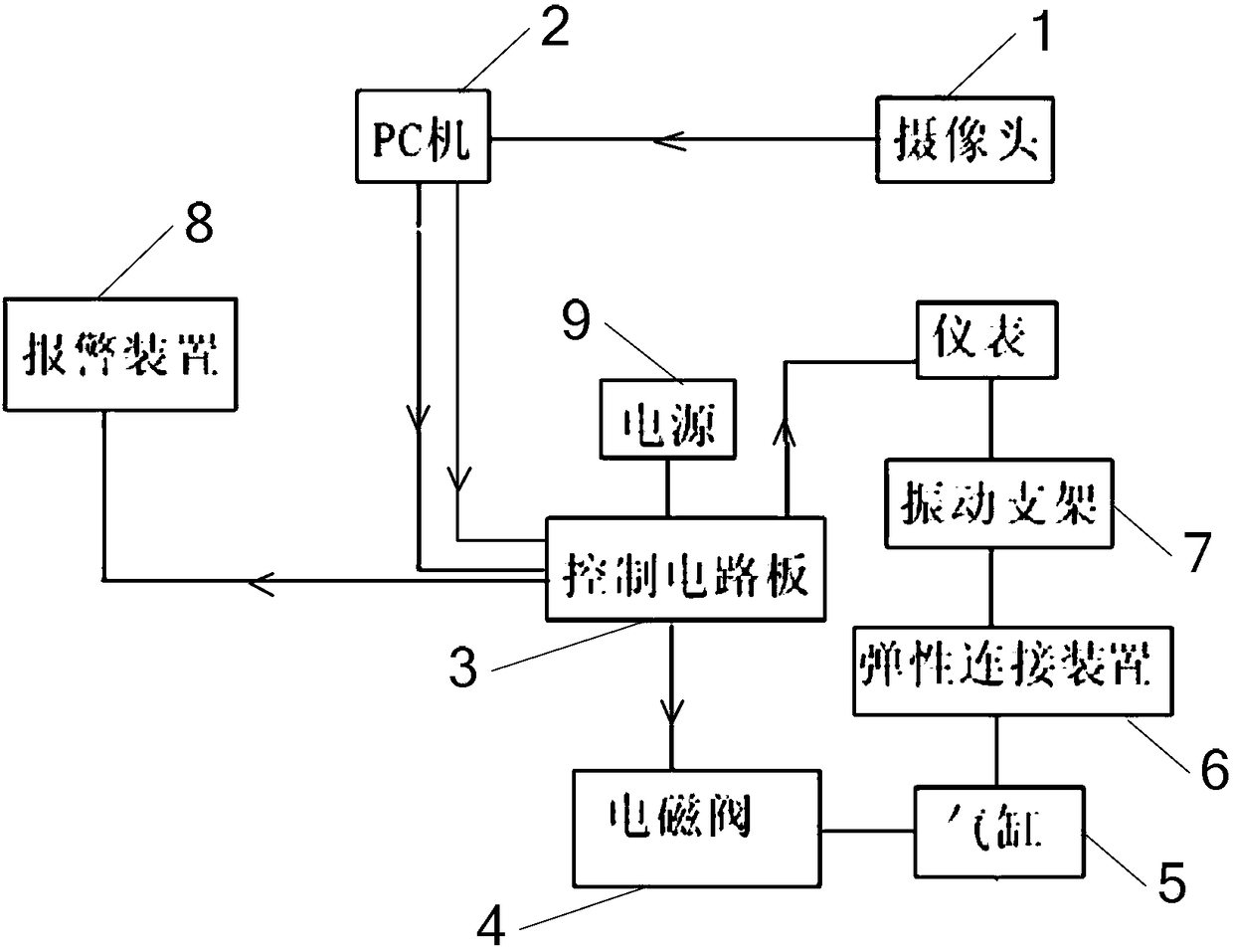
[0014] Specific implementation mode 1: see figure 1 Describe this embodiment, an adaptive tuning vibration table described in this embodiment, which includes a camera 1, a PC 2, a control circuit board 3, a solenoid valve 4, a cylinder 5, an elastic connection device 6, a vibration support 7 and an alarm device 8;
[0015] The vibration support 7 is fixed on the elastic connection device 6, and the vibration support 7 is used to fix the instrument to be measured;
[0016] The camera 1 is used to collect the image information of the instrument to be tested in real time. The data signal output end of the camera 1 is connected to the data signal input end of the PC 2, and the control signal output end of the PC 2 is connected to the control signal input end of the control circuit board 3. , the data signal output end of the PC 2 is connected with the data signal input end of the control circuit board 3;
[0017] The alarm signal output end of the control circuit board 3 is conn...
specific Embodiment approach 2
[0022] Specific implementation two: see figure 1 Illustrating this embodiment, the difference between this embodiment and the self-tuning vibration table described in Embodiment 1 is that it further includes a power source 9 , and the power source 9 is used to provide power to the control circuit board 3 .
specific Embodiment approach 3
[0023] Embodiment 3: This embodiment adopts the detection method implemented by an adaptively tuned vibration table described in Embodiment 1, and the method includes the following steps:
[0024] Step 1: The instrument to be tested remains stationary, the camera 1 captures the vibration image of the instrument to be tested in real time, the PC 2 sends a low-frequency signal to the control circuit board 3, and the low-frequency signal is sent incrementally from the starting value at 0.05Hz intervals until the final value At the same time, the control circuit board 3 sends data signals to the instrument to be tested, so that the instrument to be tested is in a normal working state;
[0025] Step 2: The control circuit board 3 outputs a control signal to control the solenoid valve 4 to close, so that the air cylinder 5 starts to work, and the movement of the air cylinder 5 drives the elastic connection device 6 and the vibration support 7 to be linked in turn, so that the instrum...
PUM
 Abstract
Description
Claims
Application Information
 - Generate Ideas
- Intellectual Property
- Life Sciences
- Materials
- Tech Scout
- Unparalleled Data Quality
- Higher Quality Content
- 60% Fewer Hallucinations
Browse by: Latest US Patents, China's latest patents, Technical Efficacy Thesaurus, Application Domain, Technology Topic, Popular Technical Reports.
© 2025 PatSnap. All rights reserved.Legal|Privacy policy|Modern Slavery Act Transparency Statement|Sitemap|About US| Contact US: help@patsnap.com

