
Vibration system, control method and electronic equipment of a linear motor group

A linear motor and vibration system technology, applied in the field of electronic equipment and linear motor group vibration system, can solve the problems of vibration attenuation, motor vibration intensity reduction, cost increase, etc., to achieve the effect of increasing vibration intensity

Active Publication Date: 2020-11-10
TRULY OPTO ELECTRONICS
View PDF5 Cites 0 Cited by
  • Summary
  • Abstract
  • Description
  • Claims
  • Application Information

AI Technical Summary

Problems solved by technology

However, the performance of different linear motors varies greatly due to different individuals, especially different motors generally have different resonant frequencies, and the difference in resonant frequency will cause many problems when multiple linear motors vibrate together, and even vibrate in severe cases attenuation of
Strictly controlling the resonant frequency range of multiple linear motors in the process will lead to a significant increase in cost
If all linear motors are driven with the same drive frequency, the vibration intensity of the motor whose drive frequency deviates more from the resonance frequency will be greatly reduced

Method used


Image

  • Vibration system, control method and electronic equipment of a linear motor group
  • Vibration system, control method and electronic equipment of a linear motor group
  • Vibration system, control method and electronic equipment of a linear motor group

Examples


Embodiment 1

[0030] see Figure 1~Figure 4 , an embodiment of the present invention provides a control method for a vibration system of a linear motor group.

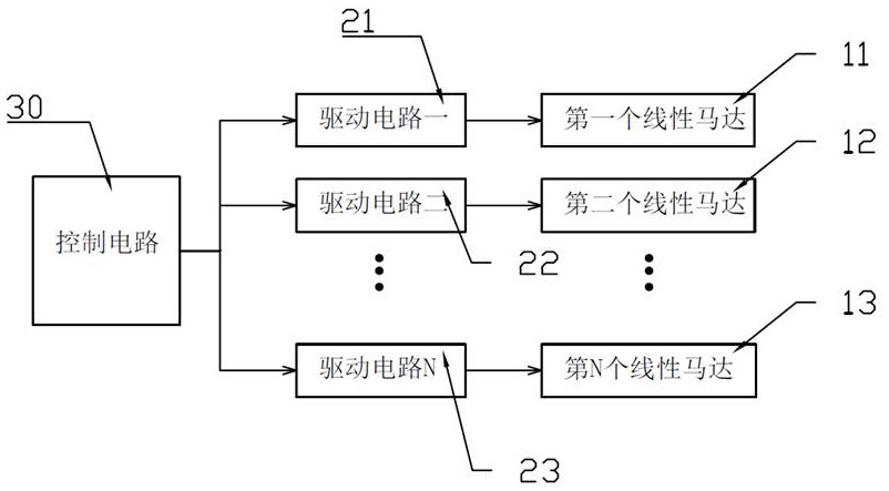
[0031] As shown in FIG. 1 , the linear motor group vibration system includes a drive circuit, a control circuit 30 and a linear motor group. The vibration part of the vibration system is a linear motor group, the linear motor group includes a plurality of linear motors, the number of linear motors is N, and N>=2. The linear motor group includes a first linear motor 11 and a second linear motor 12 . . . Nth linear motor 13 . The control circuit 30 and the drive circuit are a control section. The control circuit 30 is electrically connected to the linear motor group, and the driving circuit is electrically connected to the control chip.

[0032] The number of drive circuits is the same as the number of linear motors, and the number is also N. The drive circuits include drive circuit one 21 and drive circuit two 22 . . . Drive...

Embodiment 2

[0052] This embodiment provides a linear motor group vibration system. The vibration system includes a driving circuit, a control circuit 30 and a linear motor group. The control circuit 30 is electrically connected to the linear motor group, and the driving circuit is electrically connected to the control chip. The number of linear motors in the linear motor group is N>=2, the number of drive circuits is the same as the number of linear motors, and the control circuit 30 is electrically connected to the N drive circuits at the same time. The control method of the vibration system of the linear motor group is as described in the first embodiment.

[0053] The vibration system includes a driving chip and a control chip. The driving chip is provided with N driving circuits, and the control chip is provided with a control circuit 30 . The control chip is electrically connected to the linear motor group, and the driving chip is electrically connected to the control chip. The dr...

Embodiment 3

[0055] The present invention also provides an electronic device, the electronic device includes a display module, and the electronic device further includes a linear motor group vibration system as described in the second embodiment. The linear motor group of the linear motor group vibration system is generally arranged on the back of the display module, for example, connected by means of gluing or bracket fixed connection. The linear motor group works under the operation of the control circuit and the driving circuit, so that the display module can obtain sufficient vibration.

[0056] Specifically, the display module includes a touch screen and a display screen. The display module is an existing display module in the field, and details will not be repeated here.

[0057] Compared with the prior art, the beneficial effects of the present invention are as follows:

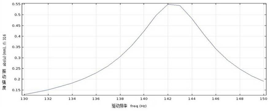
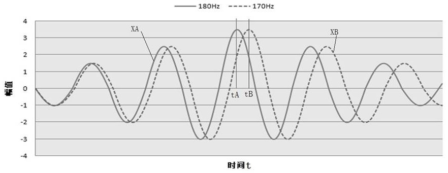
[0058] The present invention uses the drive circuit to drive the corresponding linear motor with the resonant ...


PUM


Abstract

The invention discloses a linear motor group oscillatory system, and a control method thereof. The oscillatory system comprises driving circuits, a control circuit and a linear motor group; the control circuit is electrically connected with the linear motor group, and the driving motor is electrically connected with a control chip; each driving circuit is connected with a linear motor correspondingly, and the control circuit is electrically connected with N driving circuits at the same time; each driving circuit takes the resonant frequency of the corresponded linear motor as the driving frequency to drive the corresponded linear motor; and the starting sequence and the starting time difference of N linear motors are determined according to time t, the largest vibration amplitude of each linear motor. The invention discloses electronic equipment. According to the linear motor group oscillatory system, the control method thereof and the electronic equipment, the resonant frequency of each driving circuit is taken as the driving frequency to drive corresponded linear motor, so that maximization of the oscillatory range of linear motor monomer can be obtained; the phase difference ofthe maximized monomer oscillatory ranges of different linear motors are eliminated, and thus the oscillatory range of cooperative work of multiple linear motors is maximized.

Description

technical field [0001] The invention relates to the field of touch technology, in particular to a linear motor group vibration system, a control method and an electronic device. Background technique [0002] The touch screen is an input device that realizes human-computer interaction, and it has the advantages of intuition, simplicity, and speed. With the trend of large-screen terminal electronic equipment such as mobile phones, home appliances, and vehicles, the size and weight of display touch modules are getting larger and heavier. The display and touch modules of these products generally use linear motors for vibration drive. However, limited by the size and performance of linear motors, it is difficult for a single linear motor to provide sufficient vibration. Therefore, it is a relatively obvious trend to use multiple linear motors to work together to obtain sufficient and uniform vibration. However, the performance of different linear motors varies greatly due to d...

Claims


Application Information

Patent Timeline
Patent Type & Authority Patents(China)
IPC IPC(8): H02P5/46H02P1/58
Inventor 王治玺李志成
Owner TRULY OPTO ELECTRONICS
Learn More