Lock control non-return joint ball valve

A joint ball and check technology, which is applied in the direction of control valves, valve details, valve devices, etc., can solve the problems of lack of lockable check ball valves with joints, etc., to eliminate the hidden danger of screw loss, compact structure, and reduce safety hazards Effect

Inactive Publication Date: 2016-08-17
CHONGQING SHANCHENG GAS EQUIP
View PDF6 Cites 3 Cited by
  • Summary
  • Abstract
  • Description
  • Claims
  • Application Information

AI Technical Summary

Problems solved by technology

The check ball valve is a kind of ball valve that can prevent fluid backflow. The joint ball valve is equipped with joints at one or both ends of the ball valve to form a fixed installation length to facilitate installat

Method used


Image

  • Lock control non-return joint ball valve
  • Lock control non-return joint ball valve
  • Lock control non-return joint ball valve

Examples


Embodiment 1

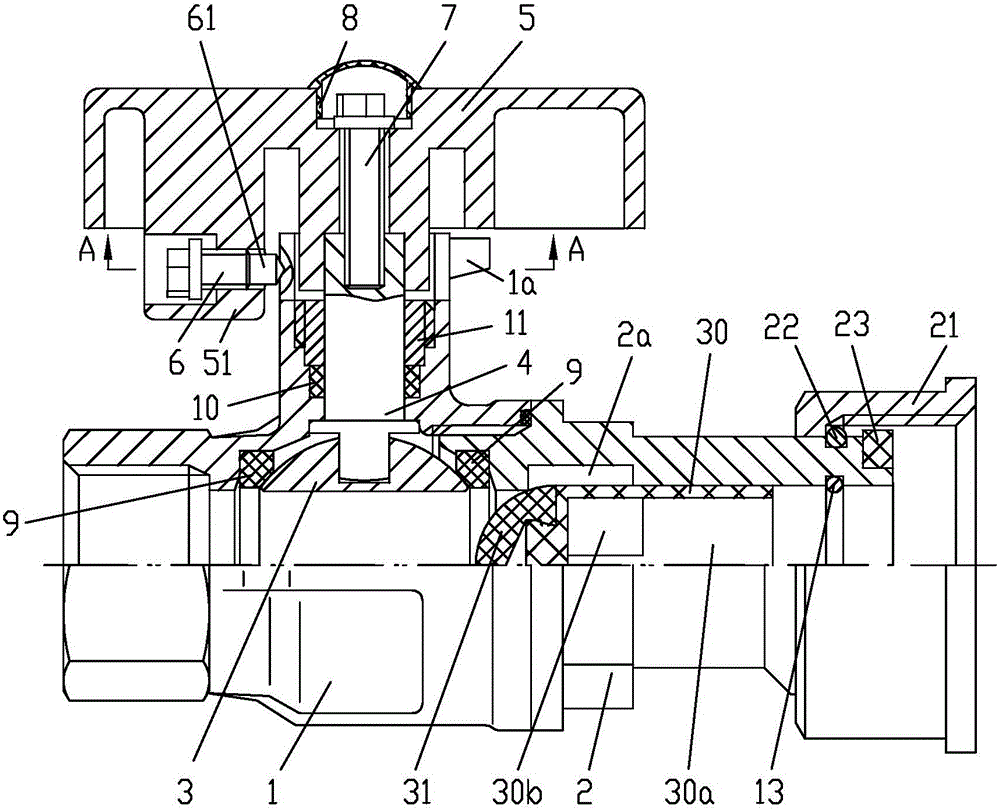
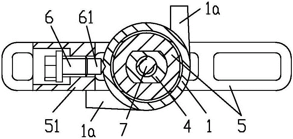
[0022] Example 1, see figure 1 , figure 2 , image 3 , a lock control check joint ball valve, comprising a valve body 1 and a valve cover 2, the external interface of the valve cover 2 constitutes a flexible joint structure, and a check valve structure is formed on the fluid passage of the valve cover 2; the valve body 1 and the valve cover The valve core 3 is connected between the cover 2 through the sealing seat ring 9, the valve core 3 is connected with the wrench 5 through the valve stem 4; There is a sealing packing 10 between the inner wall of the packing chamber, and the sealing packing 10 is pressed by the packing nut 11 to form a sealed connection between the valve stem 4 and the valve body 1; the wrench 5 is T-shaped, and the wrench 5 passes through the middle of the T-shaped The vertical part is sleeved on the outer end of the valve stem 4, and forms a torque transmission structure through two parallel flat surfaces, and the outer end of the valve stem 4 is hidde...

Embodiment 2

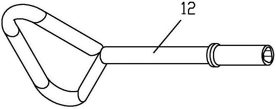
[0026] Example 2, see Figure 4 , the locking screw 6 is screwed on the outer wall of the stuffing chamber of the valve body 1, and the limit stop tongue 51 is located outside the head of the lock screw 6, so that when the lock screw 6 is tightened, the wrench 5 can rotate, and the limit stop tongue There is a perforation 52 horizontally on the 51, and the diameter of the perforation 52 is larger than the outer diameter of the screw opening tool 12 that can be inserted into the section, so that the locking screw 6 can be turned by the screw opening tool 12, so that the head of the locking screw 6 can extend into a part of the perforation 52, Thereby, the locking of the wrench 5 is formed; or, the locking screw 6 is twisted by the screw opening tool 12, so that the head of the locking screw 6 escapes from the perforation 52 and is positioned inside the limit stop tongue 51, thereby releasing the locking state of the wrench 5.

[0027] The rest of the structure of this embodimen...

Embodiment 3

[0028] Example 3, see Figure 5 , Image 6 , the head 61 of the locking screw 6 is formed with a triangular hole-shaped tightening structure, so as to be screwed only by the screw opening tool 12a matched therewith, and the screw opening tool 12a has a tightening structure with the front end of the locking screw 6 Matching triangular prism-shaped head.

[0029] The rest of the structure of this embodiment is the same as that of Embodiment 1, and will not be repeated here.


PUM


Abstract

The invention discloses a lock control non-return joint ball valve. The lock control non-return joint ball valve comprises a valve body, a valve cover and a valve element. The valve element is connected with a wrench through a valve rod. The valve rod is located in a padding bin arranged on one side of the valve body. A limiting stop tongue for limiting the rotation angle range of the wrench is formed on the wrench. A flexible joint structure is formed by an outer connection connector of the valve cover. A one-way valve structure is formed on a fluid channel of the valve cover. A locking screw with a three-prism screwing structure formed at the head part is arranged between the limiting stop tongue and the outer wall of the padding bin of the valve body and used for locking the wrench through the outer wall of the padding bin. When the locking screw only disengages from the outer wall of the padding bin or the limiting tongue, the wrench is unlocked. The lock control non-return joint ball valve has the beneficial effects that fluid backward flowing and mistaken valve opening or arbitrary valve opening can be effectively prevented, using is safe, and locking and unlocking operation is convenient; and hidden danger of locking screw losing is avoided, the lock control non-return joint ball valve is used in a household fuel gas pipeline, and the hidden danger that a gas path and a water path are mistakenly connected, and consequently tap water backwards flow into the fuel gas pipeline can be effectively eliminated.

Description

technical field [0001] The invention relates to a ball valve, in particular to a ball valve with a lock control check joint. Background technique [0002] Ball valve is a commonly used valve in the chemical industry, gas transmission, urban gas supply, and tap water supply pipelines. It has simple structure, reliable switch and long service life. Therefore, it is widely used in the above fields. Ordinary structure ball valves can be directly controlled by users as needed, and have control freedom and flexibility for direct users, but they lose control for gas supply and water supply management units. When the front-end engineering construction is not completed or the gas and water supply conditions are not met, after the valve is misoperated or operated without authorization, there will be safety hazards of tap water and gas leakage, or the risk of being stolen. The existing means of preventing unauthorized opening of the valve mainly includes designing the valve stem pull...

Claims


Application Information

Patent Timeline
IPC IPC(8): F16K5/06F16K35/10F16K41/02F16K15/06F16K15/18
CPCF16K5/06F16K5/0694F16K15/06F16K35/10F16K15/1848
Inventor 赵小波
Owner CHONGQING SHANCHENG GAS EQUIP
Why Eureka
Try Eureka