
Brake disc machining knife and machining method thereof

A technology for processing cutting tools and brake discs, which is applied in the direction of manufacturing tools, metal processing equipment, and cutting tools for lathes, etc. It can solve the problems that the processing accuracy cannot be guaranteed, and achieves avoiding unstable vibration, high-precision positioning, and ensuring connection strength. Effect

Active Publication Date: 2016-08-17
布雷博惠联(廊坊)制动系统有限公司
View PDF4 Cites 7 Cited by
  • Summary
  • Abstract
  • Description
  • Claims
  • Application Information

AI Technical Summary

Problems solved by technology

The traditional processing method is the convex surface of the rough and fine car brake disc - the concave surface of the rough car brake disc - the concave surface of the finished car brake disc. This method is efficient, but it needs to change the clamping method in different processes, the wheel mounting surface The hub mounting surface and the center hole are processed in different processes. Due to clamping errors and processing thermal deformation, the processing accuracy cannot guarantee the requirements of 0.015mm circumferential thickness difference, 0.025mm runout of the wheel mounting surface, and 0.04mm straightness requirements. , and flatness requirements of 0.03mm

Method used


Image

  • Brake disc machining knife and machining method thereof
  • Brake disc machining knife and machining method thereof
  • Brake disc machining knife and machining method thereof

Examples


Embodiment Construction

[0045] Below in conjunction with accompanying drawing and embodiment the present invention is described in further detail:

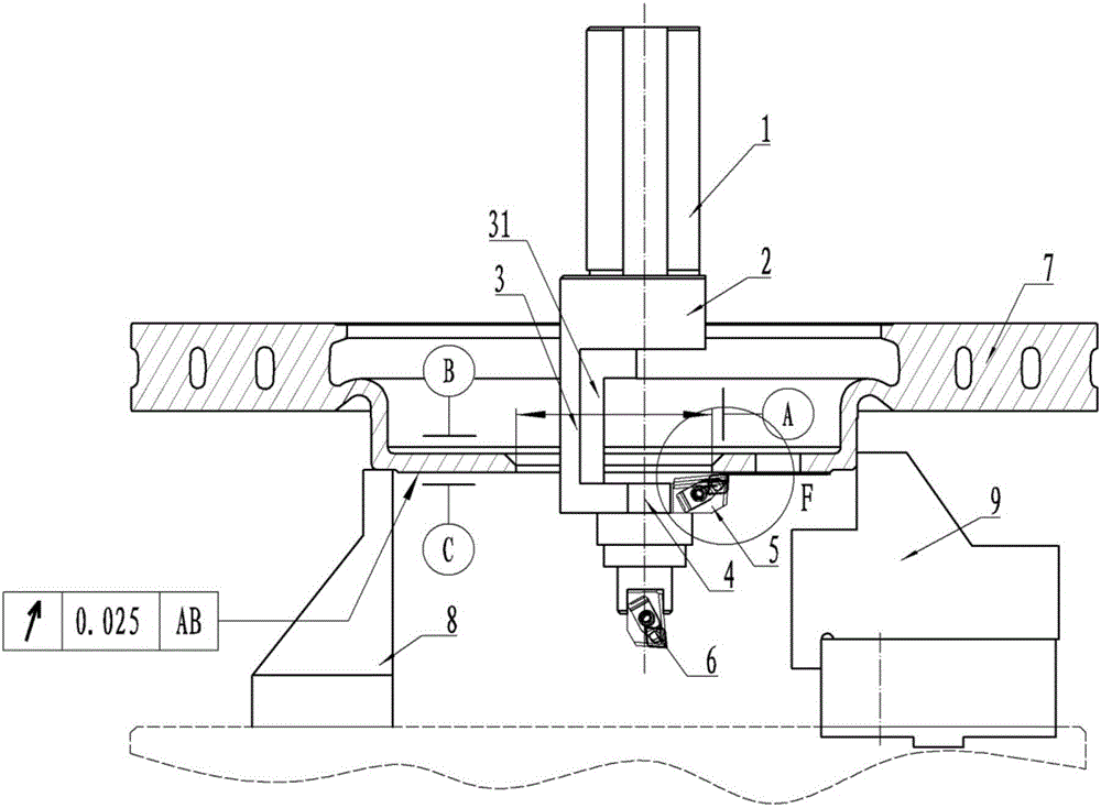
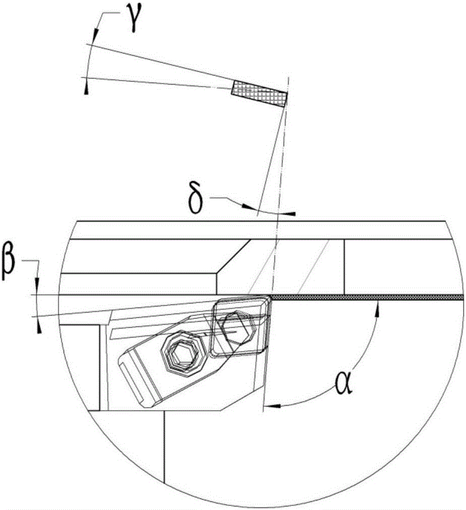
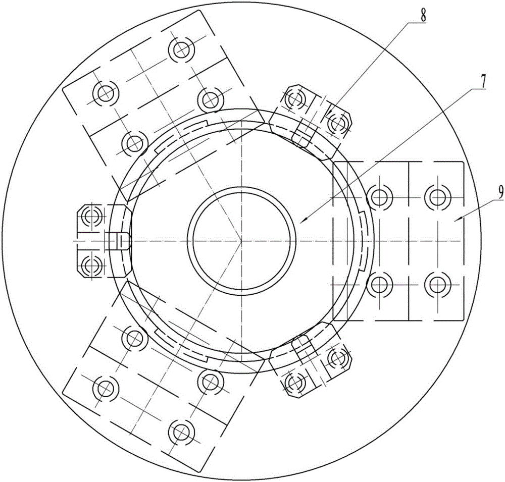
[0046] A brake disc processing tool, such as Figure 1 to Figure 13 As shown, the brake disc 7 is a disc-shaped part with a boss, and the center of the brake disc 7 is provided with a central hole. One side protruding from the boss is a convex surface, which is the wheel mounting surface C, and the other side is a concave surface, which is the hub mounting surface B. , the axis of the center hole is the datum A. The brake disc 7 is positioned with the convex surface of the boss, three positioning blocks 8 are arranged below the convex surface, the positioning blocks 8 are against the pre-processed positioning edge at the edge of the convex surface, and three clamping claws 9 are arranged on the outer surface of the boss. In order to ensure the positioning accuracy, after the positioning surfaces of the three positioning blocks are processed, they are fina...


PUM

PropertyMeasurementUnit
surface smoothnessaaaaaaaaaa

Abstract

A brake disc machining knife comprises a knife rod, a transition hook and a knife body. The knife rod is of a structure of a round rod, three vertical clamping faces in clamp fit with the knife rod machined on a cylindrical face of the round rod, the transition hook comprises a connecting disc, a side column and an underframe which are integrally machined, the connecting disc is coaxially fixed at the lower end of the knife rod, the side column is smoothly connected at the outer edge of the connecting disc and extends downward, the underframe is connected at the lower end of the side column and is a cylinder coaxial with the connecting disc and provided with a knife body mounting groove, the knife body comprises a radial knife radially mounted on the underframe, and a knife tip of the radial knife is positioned on one side opposite to the side column and points above. By using the brake disc machining knife, a measuring reference and a measuring plane are machined in a same process according to a same machining reference, machining accuracy is improved, and errors caused by repeated clamping during machining in different processes are avoided.

Description

technical field [0001] The invention relates to a processing tool and a processing method thereof, in particular to a tool suitable for processing the end face of a brake disc and a processing method thereof. Background technique [0002] The brake disc plays a vital role in the braking system of the car. A brake disc with excellent performance is one of the prerequisites for the safe driving of the car. Therefore, the shape and position tolerance of the brake disc is strictly required in the design. The difficulty also increases accordingly. [0003] See attached figure 1 , The brake disc is a disc-shaped part with a boss and a central hole, with a thinner thickness. The convex side is the wheel mounting surface C, and the concave side is the hub mounting surface B. For a brake disc, the circumferential thickness difference between the wheel mounting surface C and the hub mounting surface B is required to be 0.015mm; the runout of the wheel mounting surface is required to...

Claims


Application Information

Patent Timeline
Patent Type & Authority Applications(China)
IPC IPC(8): B23B27/00B23B1/00
CPCB23B1/00B23B27/00
Inventor 王剑刚杨盼林范亚姣张蒙
Owner 布雷博惠联(廊坊)制动系统有限公司
Learn More