
Combined device for washing tail gas and treating waste water of low-speed diesel engine of ship

A tail gas washing and wastewater treatment technology, which is applied in the direction of gaseous effluent wastewater treatment, gas treatment, water/sewage treatment, etc., can solve the problems of multiple reaction vessels, large energy consumption and high cost of oxidation devices, and achieve enhanced micro-mixing, installation Easy maintenance and small gas phase pressure drop

Inactive Publication Date: 2016-08-17
HARBIN ENG UNIV
View PDF3 Cites 16 Cited by
  • Summary
  • Abstract
  • Description
  • Claims
  • Application Information

AI Technical Summary

Problems solved by technology

This scheme consumes a lot of energy for plasma discharge, and there are many reaction vessels and large volumes. It is difficult to remove nitrate in the washing wastewater after the reaction.
[0007] The patent "A new type of wet ship exhaust gas comprehensive treatment method and device (201510175989.4)" is to treat the exhaust gas through seawater, strong oxidizing, strong acidic solution and strong reducing, strong alkaline solution in sequence, or through a pre-oxidizer , and then removed by a washing device to obtain clean tail gas and waste liquid. The waste liquid is discharged to the sea after being diluted with seawater. The various strong redox agents mentioned in the scheme have high costs, and the oxidation device consumes a lot of energy. The economy is not suitable for ships, and the way to deal with waste liquid is to dilute with seawater, which cannot fundamentally solve the pollution problem
[0008] The patent "a treatment device for waste liquid of ship washing and desulfurization system (201310259855.1)" is to remove oil slicks, Emulsified oil, particles and heavy metal hydroxide precipitation, etc., but cannot remove nitrate in washing liquid

Method used


Image

  • Combined device for washing tail gas and treating waste water of low-speed diesel engine of ship

Examples


Embodiment Construction

[0018] The present invention is described in more detail below in conjunction with accompanying drawing example:

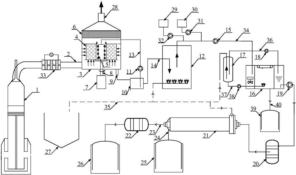
[0019] combine figure 1 , The compound device for exhaust gas washing and wastewater treatment of marine low-speed diesel engines of the present invention mainly includes: a high-gravity exhaust gas washing system and a wastewater treatment system. The high-gravity tail gas scrubbing system mainly includes: high-gravity scrubber 3, catalytic oxidation reactor 33, circulation pump 11, buffer tank 10; wastewater treatment system includes: aeration tank 12, dissolved air tank 17, air flotation tank 16, activated carbon filter 20. Reverse osmosis membrane reactor 21, precision filter 22, concentrated brine storage tank 25, clean water storage tank 26; wherein the supergravity washing tower 3 includes: packing layer 4, demister 6, liquid distributor 5, motor 7 . The exhaust gas discharged from the engine 1 passes through the exhaust pipeline 2, and is connected to th...


PUM


Abstract

The purpose of the present invention is to provide a composite device for marine low-speed diesel engine tail gas washing and wastewater treatment, including a high-gravity tail gas washing system, a wastewater treatment system, and a plasma catalytic reactor to oxidize nitrogen oxides to achieve the purpose of simultaneous absorption of exhaust gas pollutants. The high-gravity washing tower uses high-speed rotating packing to generate a super-gravity field that is hundreds to thousands of times the acceleration of gravity, so that the flow rate of the liquid film is 10 times higher than that in the gravity field. It strengthens the microscopic mixing between the gas and liquid phases, and greatly enhances the mass transfer between the gas and liquid. It has the characteristics of small equipment volume, small gas phase pressure drop, and convenient installation and maintenance. The wastewater treatment system adopts the combination of classic water treatment technology and reverse osmosis membrane treatment technology to meet the discharge standards of polycyclic aromatic hydrocarbons, turbidity, nitrates, heavy metals and other pollutants in ship wastewater stipulated by IMO.

Description

technical field [0001] The invention relates to a diesel engine tail gas treatment device, in particular to a marine diesel engine tail gas treatment device. Background technique [0002] With the rapid development of the shipbuilding industry in recent years, the NOx, SO 2 And the content of particulate matter is further increased, and the requirements for the control of exhaust emissions are becoming more and more stringent. NOx and SO emitted into the air by marine main and auxiliary engines, oil-fired boilers and incinerators 2 And particulate matter will cause great harm to humans and the environment. The Chinese government has also formulated corresponding regulations on the discharge of ship exhaust pollutants, and determined the core port area in the emission control area. [0003] The best measures to remove sulfur oxides and nitrogen oxides in the tail gas of low-speed ships are usually wet scrubbing technology and SCR technology. To achieve the purpose of simult...

Claims


Application Information

Patent Timeline
Patent Type & Authority Applications(China)
IPC IPC(8): B01D53/92B01D53/94B01D53/56B01D53/78B01D53/50B01D53/18B01D47/06B01D47/14C02F9/04C02F101/32C02F101/16C02F101/20C02F103/18
CPCB01D53/92B01D47/06B01D47/14B01D53/1481B01D53/18B01D53/50B01D53/78B01D53/9409B01D2251/104B01D2258/012B01D2259/818C02F1/001C02F1/24C02F1/441C02F1/72C02F9/00C02F2101/101C02F2101/163C02F2101/20C02F2101/327C02F2103/18
Inventor 周松周金喜朱元清王占广高瑞锋刘佃涛冯永明
Owner HARBIN ENG UNIV
Learn More