
Phase detection device and system of engine

A phase detection and engine technology, applied in engine components, engine control, machine/engine, etc., can solve problems such as affecting engine start-up performance, system safety hazards, and failing to meet the timing control requirements of 3-cylinder engines. Reduced startup time, enhanced robustness, and improved performance

Inactive Publication Date: 2016-08-10
CHINA FIRST AUTOMOBILE
View PDF4 Cites 20 Cited by
  • Summary
  • Abstract
  • Description
  • Claims
  • Application Information

AI Technical Summary

Problems solved by technology

At present, there are many inventions and designs for the crankshaft and camshaft of 4- and 6-cylinder engines, but they cannot meet the timing control requirements of 3-cylinder engines well, and the traditional detection method requires a working cycle to determine the phase of the engine, which affects engine start performance
In addition, in the traditional control method, when the crankshaft signal fails, the engine stops working immediately, which brings hidden dangers to the safety of the system

Method used

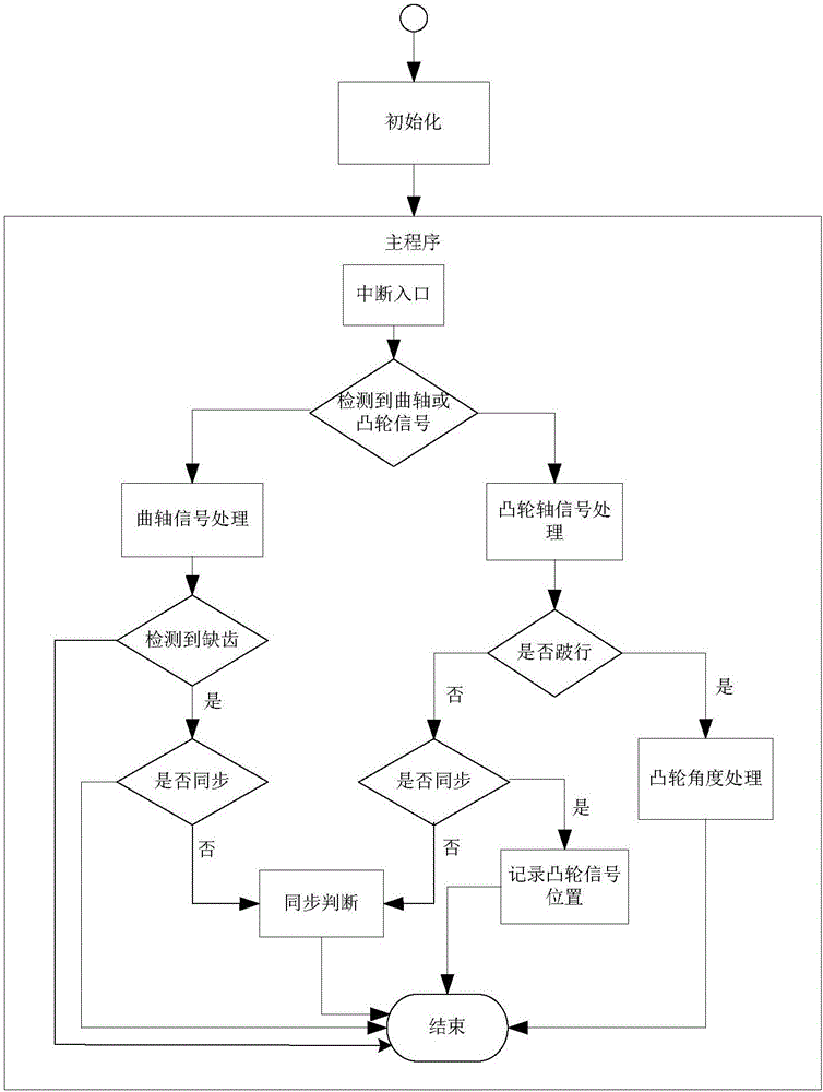
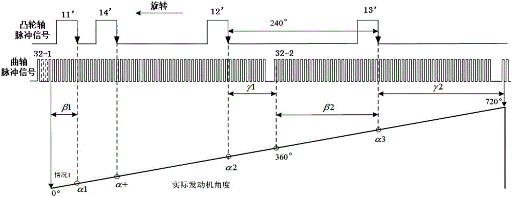

Image

  • Phase detection device and system of engine
  • Phase detection device and system of engine
  • Phase detection device and system of engine

Examples


Embodiment Construction

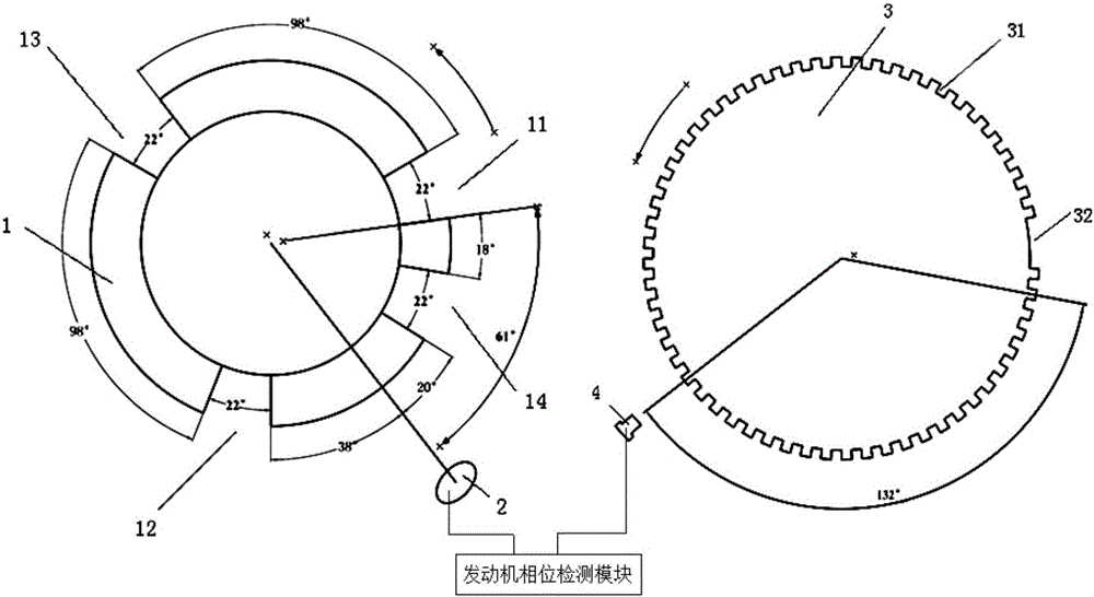
[0021] like figure 1 As shown, the engine phase detection device of the present invention includes a camshaft signal disc 1 installed and fixed on the camshaft, a first Hall sensor 2, a crankshaft signal disc 3 installed and fixed on the crankshaft, a second Hall sensor 4, and an engine Phase detection module.

[0022] The first, second, third normal teeth 11, 12, 13 and one increased tooth 14 are distributed at equal intervals on the edge of the camshaft signal plate 1, and the increased tooth 14 is located between the first and second normal teeth 11, 12 and Close to the first normal tooth 11, each normal tooth is spaced 240° apart.

[0023] The crankshaft signal plate 3 adopts the signal form of N-α teeth (N equally spaced teeth remove the adjacent α teeth, N usually takes the equivalent value of 60, 36, and α usually takes the equivalent value of 1, 2, 3), that is, the crankshaft In addition to the evenly spaced teeth 31, there is also a missing tooth 32 on the edge of t...


PUM


Abstract

The invention relates to a phase detection device of an engine. A cam shaft signal panel of the device is fixedly installed on a cam shaft. A crankshaft signal panel is fixedly installed on a crankshaft. Three normal teeth and an extra tooth are distributed at the edge of the cam shaft signal panel at equal intervals, and the extra tooth is located between two of the three normal teeth. N continuous equally-spaced teeth and a missing tooth are distributed at the edge of the crankshaft signal panel. A first Hall sensor is fixed to the edge of the cam shaft signal panel, and a second Hall sensor is fixed to the edge of the crankshaft signal panel. A cam shaft pulse signal which is generated by the first Hall sensor and represents cam shaft phase information and a crankshaft pulse signal which is generated by the second Hall sensor and represents crankshaft phase information are transmitted to an engine phase detection module. The engine phase detection module carries out analysis treatment on the cam shaft pulse signal and the crankshaft pulse signal so that engine phase data can be obtained. By means of the phase detection device of the engine, the start time of the engine is shortened, performance of an electric control system of the engine is improved, and the robustness of the electric control system is enhanced.

Description

Technical field: [0001] The invention belongs to the field of engine electronic control systems, and relates to an engine phase detection device and a detection system. Background technique: [0002] Engine phase detection is a core content of the timing control of the electronic control system. It is the basis for performing fuel injection and ignition controls. Fast and accurate determination of the engine phase can shorten the starting time of the engine, thereby improving the performance of the electronic control system. [0003] In one working cycle of the engine, the crankshaft rotates two revolutions and the camshaft rotates one revolution, that is, one working cycle is 720 ° crankshaft angle (the angle unit is uniformly represented by the crankshaft angle). When the engine is working normally, it is necessary to determine the engine phase according to the phase relationship of the input crankshaft and camshaft signals, so as to provide angles for the control of fuel ...

Claims


Application Information

Patent Timeline
Patent Type & Authority Applications(China)
IPC IPC(8): F02D41/00F02D41/30F02B77/08
CPCF02D41/009F02B77/087F02D41/3005
Inventor 刘时珍吕贵林陈涛
Owner CHINA FIRST AUTOMOBILE
Learn More