Production process of rubber diaphragm in automobile brake air chamber

A technology of rubber diaphragm and automobile brake, which is applied in the field of automobile brake system, and can solve the problems of difficult operation, wrinkling, and inability to be evenly centered, etc.

Inactive Publication Date: 2016-08-10
DATWYLER SEALING TECH ANHUI
View PDF5 Cites 2 Cited by
  • Summary
  • Abstract
  • Description
  • Claims
  • Application Information

AI Technical Summary

Problems solved by technology

[0003] For example, the patent No. 200910249742 is the invention patent "Production process of rubber diaphragm of automobile brake chamber". Although the problem of over-vulcanization of the lower rubber layer has been solved to a certain extent, after the first pre-vulcanization molding, the lower rubber layer and the cloth have been pre-vulcanized into a sparse shape, while the rubber block of the upper mold has not been pre-formed, and the product is easy to Wrinkles, leaking cloth, unable to be evenly centered, resulting in a single side of the diaphragm wall thickness, low pass rate, and the middle mold needs to be turned over with a hinge during the second vulcanization, which is difficult to operate and poor in safety
[0004] For example, the patent No. 201210038464 is the invention patent "production process of rubber diaphragm of automobile brake chamber". Although the step of "diaphragm cloth-bottom adhesive layer bonding

Method used


Image

  • Production process of rubber diaphragm in automobile brake air chamber
  • Production process of rubber diaphragm in automobile brake air chamber
  • Production process of rubber diaphragm in automobile brake air chamber

Examples


Embodiment 1

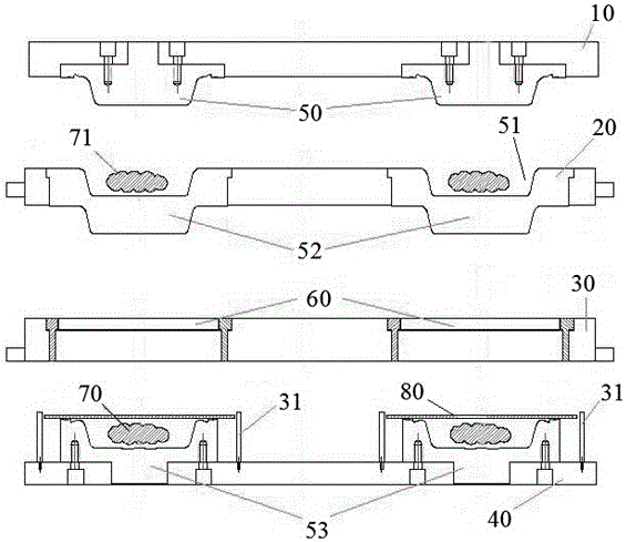
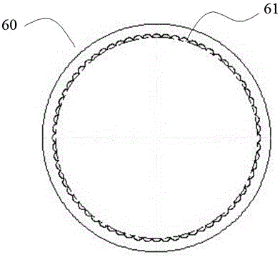
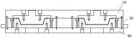
[0038] A rubber extrusion molding machine and a laser cutting machine are used to prepare the upper rubber block 71, the lower rubber block 70 and the regular cloth 80. The quality of the upper rubber block 71 and the lower rubber block 70 can be different, and an automatic flat vacuum is used. The vulcanization press and corresponding molds are used to vulcanize the rubber diaphragm. The upper rubber layer of the rubber diaphragm has a separate vulcanization time T1=10s, while the lower rubber layer material and cloth vulcanization time T1=10 seconds, the upper rubber layer and the lower rubber layer- The cloth fusion body is fully vulcanized for T2=255s, the vulcanization temperature is 145°C, the holding pressure is 19Mpa, and each time vulcanization is vacuumed for 10 seconds, holding pressure twice, and exhausted twice.

Embodiment 2

[0040] For preliminary preparations, refer to Example 1. The vulcanization time of the upper rubber layer of the rubber diaphragm is T1=12s, and the vulcanization time of the lower rubber layer material and the cloth is T1=12 seconds, and the upper rubber layer and the lower rubber layer-cloth fusion are fully vulcanized T2=258s, vulcanization temperature is 152℃, holding pressure is 18Mpa, and each time vulcanization is evacuated for 11 seconds, holding pressure three times, and exhausting twice.

Embodiment 3

[0042] For the preliminary preparation, refer to Example 1. The vulcanization time of the upper rubber layer of the rubber diaphragm is T1=15s, and the vulcanization time of the lower rubber layer material and the cloth is T1=15 seconds, and the upper rubber layer and the lower rubber layer-cloth fusion are fully vulcanized T2=262s, the vulcanization temperature is 162℃, the holding pressure is 20Mpa, and each time the vulcanization is carried out, vacuum is applied for 10 seconds, pressure is maintained twice, low pressure stays 0.8s, and exhausted three times.


PUM


Abstract

The invention relates to a production process of a rubber diaphragm in an automobile brake air chamber and belongs to the technical field of automobile brake systems. The production process comprises the steps of: 1) pre-vulcanizing an upper and a lower rubber layers; and 2) fusing the upper and a lower rubber layers. In the technical scheme, a secondary vulcanization process with the same rubber material formula and the equal vulcanization speed is provided, and by means of the process, the upper and the lower rubber layers of the diaphragm is produced through an extruder die, wherein through the vulcanization process in the equal time, vulcanization status in the upper and the lower rubber layers are completely same, so that the problem, which troubles people for a long time, of over-vulcanization of the lower rubber layer during the vulcanization shaping process can be solved, and the problems that rubber materials in different formula are complex and difficult to distinguish and fuse, which influences bonding strength, are solved. The rubber diaphragm is increased greatly in qualified rate, is effectively controlled in production cost, has excellent high-temperature and low-temperature performances, has excellent anti-aging and anti-fatigue performances, is greatly improved in total performance and service life, and has significant advantages.

Description

Technical field [0001] The invention relates to a production process of a rubber diaphragm of an automobile brake air chamber, and belongs to the technical field of automobile brake systems. Background technique [0002] The air chamber rubber diaphragm is the core component of various medium and heavy vehicle brake components with a load capacity of more than 3 tons, which is related to the safety of the vehicle. The diaphragm is required to withstand high pressures of about 0.8MPa and ensure a service life of more than 1 million times. When the air chamber diaphragm is used, when the car brakes with high air pressure, the air pressure pushes the air chamber diaphragm to push the push rod forward, and finally transmits the driving force to the brake patch in the wheel drum to achieve the purpose of braking. Developed countries such as Europe and the United States all plan to have special standards that have strict requirements on the finished product of the air chamber diaphrag...

Claims


Application Information

Patent Timeline
IPC IPC(8): B29C43/04B29C43/18B29C43/20B29C43/36B29C35/02
CPCB29C43/04B29C35/02B29C43/183B29C43/203B29C43/36
Inventor 程未栋万耀胜袁玉虎高睿周健
Owner DATWYLER SEALING TECH ANHUI
Why Eureka
Try Eureka