Sheet Metal Coordinate Grid Stamping Die

A coordinate grid, metal sheet technology, applied in metal processing equipment, forming tools, manufacturing tools, etc., can solve the problems of low grid accuracy, high scrap rate, grid damage, etc. Stable quality effect

Inactive Publication Date: 2018-04-24
JIANGSU UNIV
View PDF9 Cites 0 Cited by
  • Summary
  • Abstract
  • Description
  • Claims
  • Application Information

AI Technical Summary

Problems solved by technology

[0003] In practice, it is found that the coordinate grid generated by the traditional coordinate grid printing technology will have defects such as grid damage due to extrusion and wear after stamping, which will bring great errors to the subsequent strain measurement
At the same time, using the traditional coordinate grid printing technology to generate a grid requires a lot of preparatory work, which takes a long time, especially when the number of products is relatively large, it often takes a lot of time to complete the grid printing work , and the scrap rate is high
For example, the scribing method, although the equipment is simple, but the grid accuracy is too low, the scribing depth is too deep, which easily affects the quality of the sheet metal forming; the rubber printing method, the printed grid accuracy is not high, and the resolution is limited; The grid prepared by the missing printing method is easy to cause different grid depths; the contact photography method takes a long time and the equipment is large; the electrochemical corrosion method consumes a lot of energy, and the electrolyte is easy to damage the environment. create pollution

Method used


Image

  • Sheet Metal Coordinate Grid Stamping Die
  • Sheet Metal Coordinate Grid Stamping Die
  • Sheet Metal Coordinate Grid Stamping Die

Examples


Embodiment Construction

[0039] The specific structure of the present invention and its implementation will be further described below through examples and with reference to the accompanying drawings.

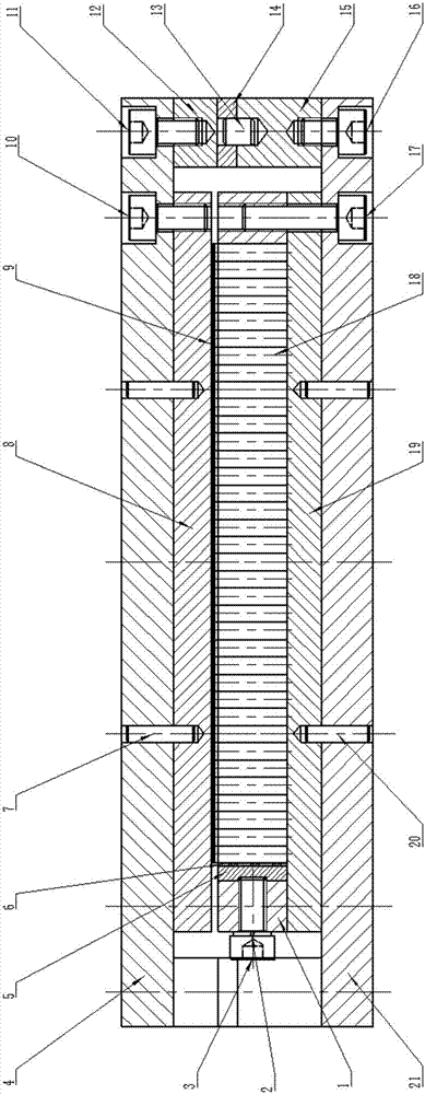
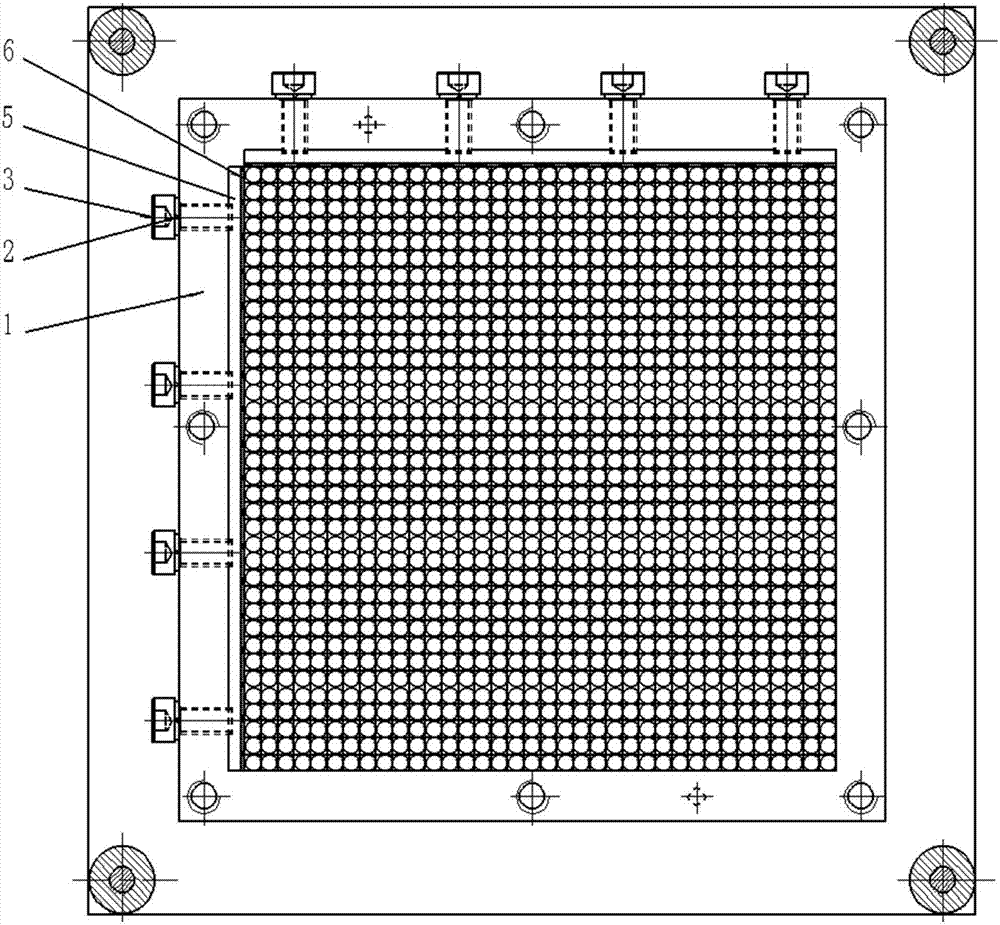
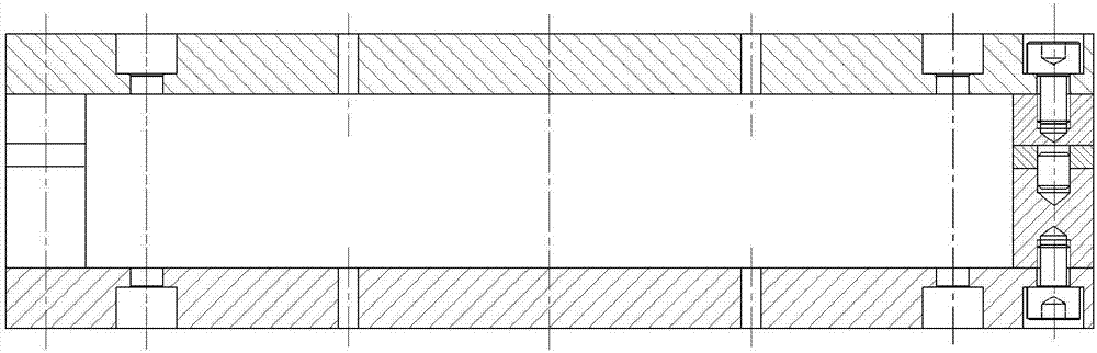
[0040] like figure 1 As shown, the metal sheet coordinate grid stamping die described in the patent of the present invention is composed of the following parts: ring fixing plate 1, spring washer 2, fastening bolt 3, upper template 4, clamping plate 5, rubber pad 6 , upper mold positioning pin 7, upper mold backing plate 8, sheet material 9, fastening bolt 10, fastening bolt 11, upper mold support block 12, upper and lower mold positioning pin 13, ring limit block 14, lower mold support block 15 , Fastening bolt 16, fastening bolt 17, punch 18, lower mold backing plate 19, lower mold positioning pin 20, lower template 21.

[0041] like figure 1 As shown, the metal sheet coordinate grid stamping die punch 18 described in the patent of the present invention is designed by the customer according to spec...


PUM


Abstract

The invention provides a metal sheet coordinate grid punching mold; and the metal sheet coordinate grid punching mold is mainly applied to the field of printing of metal sheet coordinate grids. The metal sheet coordinate grid punching mold consists of a working part, a positioning part and a fixing part, wherein the working part is a convex mold; the positioning part includes a dowel pin, an annular limiting block and a support block; and the fixing part includes a fastening bolt, a spring washer, an upper mold cushion plate, a lower mold cushion plate, an annular fixed plate, a clamping plate, a rubber pad, an upper template and a lower template. The metal sheet coordinate grid punching mold adopts a punching mode to print metal coordinate grids, adopts a quick change mold assembly structure design, can quickly replace and use convex molds and mold frame parts with different sizes and forms, can print the coordinate grids with different forms for metal plates with different sizes, can finish or replace the axial size of the annular limiting block according to the punching effect to adjust the depth of the punched grids, can recycle molds after production, assembly and debugging, and is simple and convenient for later use.

Description

technical field [0001] The invention provides a metal thin plate coordinate grid stamping die, belonging to the technical field of metal thin plate strain measurement coordinate grid printing. Background technique [0002] With the continuous emergence of new sheet metal parts and new materials, the research on the formability of sheet metal has become increasingly extensive and in-depth. Since the 1960s, the forming limit diagram proposed by Keeler and Goodwin is helpful to the research in this area. In order to create a forming limit diagram, a method must be found to draw a coordinate grid on the sheet. At present, there are mainly five methods for printing coordinate grids: scriber marking, rubber embossing, screen printing, contact photography, and electrochemical corrosion methods. Among them, the latter three methods are most commonly used. [0003] In practice, it is found that the coordinate grid generated by the traditional coordinate grid printing technology wi...

Claims


Application Information

Patent Timeline
Patent Type & Authority Patents(China)
IPC IPC(8): B21D37/10B21D22/02
CPCB21D22/02B21D37/10
Inventor 史鹏飞陈炜舒泽泉李宇翔杨浩郭首汛
Owner JIANGSU UNIV
Why Eureka
Try Eureka