
A method and system for generating millimeter waves

A generation method, millimeter wave technology, applied in the field of communication, can solve problems such as the adverse effects of optical carrier and high system complexity, and achieve the effects of avoiding voltage drift, low system complexity, and reducing system cost

Active Publication Date: 2018-06-29
SUZHOU UNIV
View PDF3 Cites 0 Cited by
  • Summary
  • Abstract
  • Description
  • Claims
  • Application Information

AI Technical Summary

Problems solved by technology

[0005] In view of this, the present application provides a method and system for generating millimeter waves to overcome the problems in the prior art that the system complexity is too large and the generation of optical carriers is adversely affected by the voltage drift of the DC bias voltage source

Method used


Image

  • A method and system for generating millimeter waves
  • A method and system for generating millimeter waves
  • A method and system for generating millimeter waves

Examples


Embodiment 1

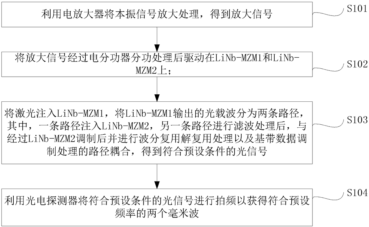
[0051] Embodiment 1 of the present application provides a method for generating millimeter waves, such as figure 1 as shown, figure 1It is a flowchart of a method for generating a millimeter wave provided in Embodiment 1 of the present application. The method includes:

[0052] S101: using an electric amplifier to amplify and process the local oscillator signal to obtain an amplified signal;

[0053] In this application, the type of the electric amplifier can be selected according to needs, which is not limited in this application; the local oscillator signal can be generated by a local oscillator, and is not specifically limited.

[0054] S102: drive the amplified signal on LiNb-MZM1 and LiNb-MZM2 after being processed by an electric power divider;

[0055] Among them, the bias points of LiNb-MZM1 and LiNb-MZM2 are both set at the maximum transmission point;

[0056] Specifically, in this application, two electrical phase shifters can be used to set the bias point of LiNb...

Embodiment 2

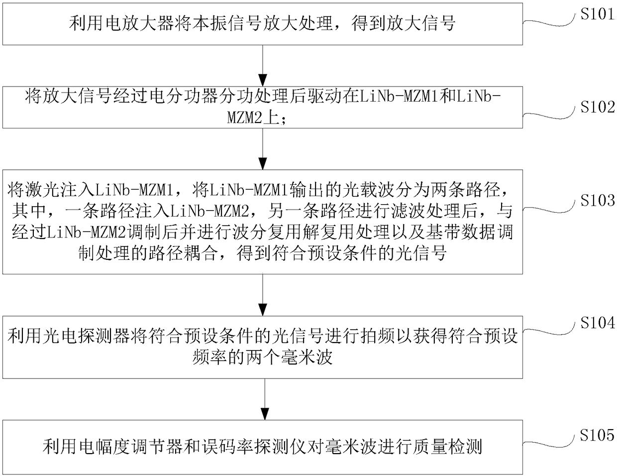
[0064] On the basis of Embodiment 1, Embodiment 2 of the present application provides another method for generating millimeter waves, such as figure 2 as shown, figure 2 It is a flow chart of a method for generating millimeter waves provided in Embodiment 2 of the present application. The method includes:

[0065] S101: using an electric amplifier to amplify and process the local oscillator signal to obtain an amplified signal;

[0066] In this application, the type of the electric amplifier can be selected according to needs, which is not limited in this application; the local oscillator signal can be generated by a local oscillator, and is not specifically limited.

[0067] S102: drive the amplified signal on LiNb-MZM1 and LiNb-MZM2 after being processed by an electric power divider;

[0068] Among them, the bias points of LiNb-MZM1 and LiNb-MZM2 are both set at the maximum transmission point;

[0069] Specifically, in this application, two electrical phase shifters ca...

Embodiment 3

[0087] On the basis of Embodiment 1, Embodiment 3 of the present application provides a millimeter wave generation system, such as Figure 4 as shown, Figure 4 It is a schematic structural diagram of a millimeter wave generating system provided in Embodiment 3 of the present application. The system includes: a signal amplification device 301, a power dividing device 302, a processing device 303 and an acquisition device 304, wherein,

[0088] The signal amplifying device 301 is used to amplify the local oscillator signal by using an electric amplifier to obtain an amplified signal;

[0089] In this application, the signal amplifying device includes a local oscillator and an electric amplifier. The electrical amplifier amplifies and processes the local oscillator signal generated by the local oscillator to obtain an amplified signal.

[0090] The power dividing device 302 is used to drive the amplified signal to the first lithium niobate Mach-Zehnder modulator LiNb-MZM1 and...


PUM


Abstract

The invention provides a method and a system for millimeter wave generation. The method comprises steps that an LiNb-MZM1 and an LiNb-MZM2 are driven by a local oscillator signal after the local oscillator signal is amplified by an electrical amplifier; laser is injected into the LiNb-MZM1, light carrier waves outputted by the LiNb-MZM1 are divided into two paths, one path of light carrier waves is injected into the LiNb-MZM2, filtering processing on the other path of light carrier waves is carried out, after modulation through the LiNb-MZM2, wavelength division multiplexing de-multiplexing processing and base-band data modulation processing on the one path of light carrier waves, path coupling for the other path of light carrier waves and the one path of light carrier waves is realized, and a photoelectric detector is utilized to carry out beat frequency of light signals acquired through coupling to acquire two millimeter waves satisfying preset frequencies. According to the method, a cascade type lithium niobate Mach-Zehnder modulator is utilized to generate coherent light carrier waves, bias points of the modulator are respectively arranged at a largest transmission point, power supply through a DC offset voltage source for the modulator is not needed, the system structure is simplified, under the condition of low system complexity, the relatively large frequency multiplication number is acquired, two millimeter waves are simultaneously generated, and system cost is reduced.

Description

technical field [0001] The present application relates to the field of communication technologies, and in particular to a method and system for generating millimeter waves. Background technique [0002] With the explosive growth of communication services in the communication system, the low frequency band is already very congested. The ultra-high frequency band, that is, the millimeter wave band (frequency bands ranging from tens of GHz to hundreds of GHz), can provide faster information transmission rates and greater Communication capacity has received more attention. [0003] At present, in optical wireless communication systems, an external modulator is generally used to generate many coherent optical carriers with the same frequency interval, and then a wavelength selective switch is used to select the two required optical carriers. One path uses an intensity modulator to modulate baseband data, and one path uses an intensity modulator to modulate baseband data. The dat...

Claims


Application Information

Patent Timeline
Patent Type & Authority Patents(China)
IPC IPC(8): H04B10/50H04B10/516H04B10/80
CPCH04B10/505H04B10/516H04B10/808
Inventor 高明义杨涛沈纲祥
Owner SUZHOU UNIV
Learn More