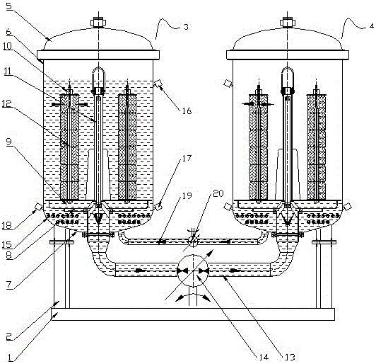
Energy-saving yarn dyeing system for dyeing

A yarn dyeing and energy-saving technology, which is applied in liquid/gas/steam yarn/filament processing, textiles and papermaking, and textile processing machine accessories, etc. It can solve problems such as poor dyeing effect, excessive dyeing liquor, and affecting processing. , to achieve the effect of ensuring the dyeing effect, solving the single dyeing, and reducing the power demand

Inactive Publication Date: 2016-08-03
NANTONG DONGGENG MACHINERY CO LTD
View PDF6 Cites 6 Cited by
  • Summary
  • Abstract
  • Description
  • Claims
  • Application Information

AI Technical Summary

Problems solved by technology

[0005] The above structure solves the problem that the dye liquor of the dyeing machine can only flow in one direction, the dyeing effect is not good, and the residue in the dye liquor cannot be discharged from the dye tank, which affects the subsequent processing.
However, when this kind of dyeing machine is performing dyeing, when performing reversing dyeing, the working direction of the circulating pump is switched through the circulating automatic reversing device, so that the dyeing liquid flows in the reverse direction and continues to dye, so it is necessary to use a more powerful circulating pump to work. , otherwise it cannot meet its needs, and the cost is high; this kind of dyeing machine can only dye one group of cheeses at a time, the work efficiency is not high, and the amount of dyeing liquid required is relatively large, and when dyeing, it is also necessary to dye The dyeing liquid is heated, and the traditional heating method is steam heating, so correspondingly, a large amount of water vapor needs to be consumed, which increases the cost; in addition, the dyeing machine can only dye cheese yarn, and the type of dyed yarn relatively single

Method used


Image

  • Energy-saving yarn dyeing system for dyeing

Examples


Embodiment Construction

[0023] The following examples can enable those skilled in the art to understand the present invention more comprehensively, but the present invention is not limited to the scope of the described examples.

[0024] Such as figure 1 The energy-saving yarn dyeing system for dyeing shown includes a fixed seat, a dyeing vat, a creel, a circulation unit, a heating unit, a detection unit and an equalizing water level unit.

[0025] The fixing seat is composed of a horizontally arranged underframe 1 and vertically arranged legs 2 installed at both ends of the underframe 1 .

[0026] There are two dyeing vats, respectively dyeing vat A3 and dyeing vat B4, dyeing vat A3 and dyeing vat B4 are symmetrically installed on the upper ends of the legs 2 at both ends of the fixing seat. The cylinder head 5 is provided with a sealing head 7 at the lower end of the cylindrical body 6, and the sealing head 7 and the cylindrical body 6 are welded into one body.

[0027] There are two groups of cr...


PUM


Abstract

The invention relates to an energy-saving yarn dyeing system for dyeing, which comprises a fixed seat, a pair of dyeing vats arranged side by side, and a pair of creels respectively installed in the two dyeing vats. A central rod is installed on the upper end, and several yarn rods are distributed around the central rod. The yarn rod is a hollow tube, the bottom end is connected with the yarn disc, the top end is sealed by a lock head, and several through holes are opened on the yarn rod; Unit, the circulation unit includes a circulation pipeline connecting two dyeing vats, and a bidirectional circulation pump A is installed on the circulation pipeline; a heating unit, the heating unit is installed on the dyeing vat, including several evenly distributed on the lower head. Heater; a detection unit, the detection unit includes a high water level probe, a low water level probe and a temperature sensor. The advantages of the present invention are: the dyeing system of the present invention can effectively reduce the power of the circulation pump, reduce the consumption of dyeing liquid and steam, reduce the production cost and improve the working efficiency.

Description

technical field [0001] The invention relates to the field of dyeing and finishing equipment used in the printing and dyeing industry, in particular to an energy-saving yarn dyeing system for dyeing. Background technique [0002] The dyeing machine is used in the dyeing, bleaching, scouring and washing processes of wool, cashmere, acrylic and cotton wool, etc. It can also be used for the bleaching and dyeing of gloves, socks, towels and other products. It is a wide range of applications. Yarn bleaching and dyeing equipment. [0003] However, in the energy-saving dyeing machines currently on the market, the dye liquor can only flow in one direction, the dyeing effect is not good, which affects the quality of fabric bleaching and dyeing, and the residue in the dye liquor cannot be discharged from the dye tank, which affects subsequent processing. [0004] There is also a dyeing machine with two-way flow of dye liquor. For example, a cheese dyeing machine is proposed in Patent ...

Claims


Application Information

Patent Timeline
IPC IPC(8): D06B3/04D06B23/14D06B23/20D06B23/22
CPCD06B3/04D06B23/14D06B23/20D06B23/205D06B23/22
Inventor 张松俊周卫凌芳孙维维张启伟张美兵
Owner NANTONG DONGGENG MACHINERY CO LTD
Why Eureka
Try Eureka