
Switching equipment stacking method and device

A switching device and cross-device technology, applied in the field of Ethernet switching, can solve problems such as poor reliability, inability to use ordinary cascading ports, and rising costs, and achieve the effect of simplifying management complexity and shortening the establishment time

Inactive Publication Date: 2016-07-27
ZTE CORP
View PDF5 Cites 10 Cited by
  • Summary
  • Abstract
  • Description
  • Claims
  • Application Information

AI Technical Summary

Problems solved by technology

Daisy-chain stacking is a simplified stacking technology that can provide excellent forwarding performance and convenient management features when there are fewer stacking levels, such as expansion ports between boards in a communication equipment chassis. However, the existing daisy-chain stacking The port is fixed and cannot be used as an ordinary cascade port
In stack management, master-slave devices are distinguished, which has certain restrictions on applications. For example, when the entire system version is managed centrally, the version is transferred to the slave switch device through the stack channel. It is very complicated and unreliable to support stack management in the boot of the master-slave device. will lead to increased costs
[0005] In short, the technical problem of this solution is that the stacking ports connected between the existing switching devices are not universal and the stacking member devices need to distinguish between master and slave

Method used


Image

  • Switching equipment stacking method and device
  • Switching equipment stacking method and device
  • Switching equipment stacking method and device

Examples


Embodiment Construction

[0043] In order to make the technical problems, technical solutions and advantages to be solved by the present invention clearer, the following will describe in detail with reference to the drawings and specific embodiments.

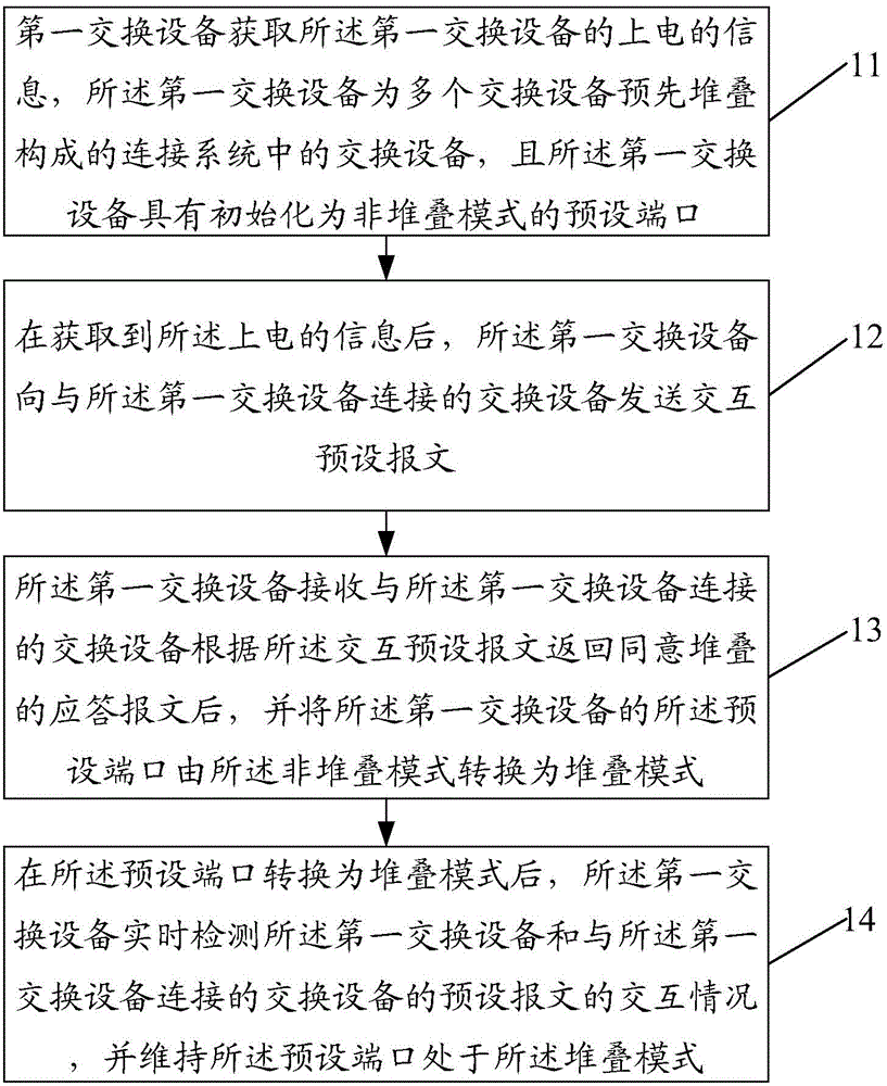
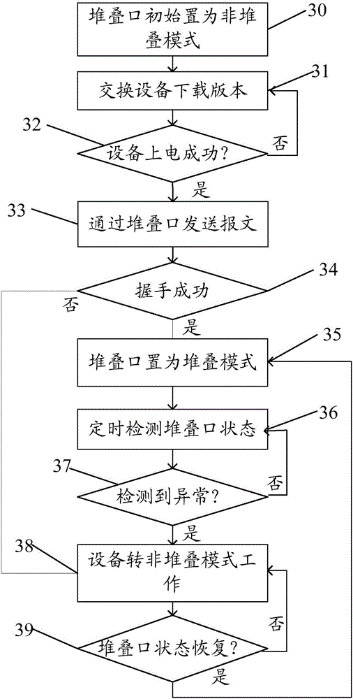
[0044] The present invention aims at the fact that in the prior art, the stacking port between chips cannot be automatically switched to work in a non-stacking mode, and the ordinary cascading application between chips cannot be realized through the stacking port, and at the same time, it does not provide stacking link reliability detection and forwarding table synchronization processing after the switch is stacked , and the stacking device also needs to distinguish the master-slave problem, a method and device for stacking switching devices are provided, by pre-initializing the preset port of the switching device to non-stacking mode, and then after the switching device is powered on, through the preset alarm The interaction of text realizes the dynamic ...


PUM


Abstract

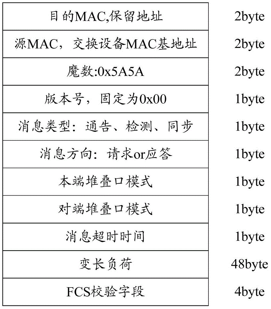
The present invention provides a switch equipment stacking method and device. The method is applied to switch equipment. The method comprises a step of obtaining the power-on information of first switch equipment which is in the connection system formed by the pre-stacking of multiple switch equipment and has a default port whose initialization is a non-stack mode, a step of obtaining the information of power-on and sending an exchange preset message to the switch equipment which is connected to the first switch equipment, a step of receiving the response message of stack approval returned by the switch equipment which is connected to the first switch equipment according to the exchange preset message, converting the preset port of the first switch equipment into a stack mode from the non-stack mode so as to realize the stack message exchange of the first switch equipment and the switch equipment which is connected to the first switch equipment, and a step of detecting the exchange condition of the first switch equipment and the preset message of the switch equipment which is connected to the first switch equipment, and maintaining the preset port in a stacked mode.

Description

technical field [0001] The invention relates to Ethernet switching technology, in particular to a method and device for stacking switching equipment. Background technique [0002] Stacking is a technology widely used to expand ports on Ethernet switches at present, and it is a non-standardized technology. Currently there are two popular stacking modes: star mode and daisy chain mode. [0003] Star stacking technology, for switches, needs to provide an independent or integrated high-speed switching center (stacking center), all stacking hosts are uplinked to a unified stacking port through a dedicated (or general-purpose high-speed port) high-speed stacking port Center, the stacking center is generally a hardware switching unit based on a dedicated ASIC (Application Specific Integrated Circuit). According to its switching capacity, the bandwidth is generally between 10-32G, and its ASIC switching capacity limits the number of stacked layers. The star stacking mode is suitab...

Claims


Application Information

Patent Timeline
IPC IPC(8): H04L12/939H04L12/24
Inventor 崔向武沈智星吴筱苏
Owner ZTE CORP
Learn More