
Heat pump type large temperature difference heat exchange system and method

A technology of heat exchange system and large temperature difference, which can be used in fluid heaters, energy-saving heating/cooling, lighting and heating equipment, etc., and can solve the problem of limiting one network

Active Publication Date: 2016-07-27
HUNAN TOWN ENERGY TECH
View PDF5 Cites 1 Cited by
  • Summary
  • Abstract
  • Description
  • Claims
  • Application Information

AI Technical Summary

Problems solved by technology

[0003] For the traditional heat exchanger system, there needs to be a certain heat transfer temperature difference between the first network water and the second network water to achieve effective heat exchange, which theoretically determines that the return water temperature of the first network water should be higher than the return water temperature of the second network water , thereby limiting the temperature difference between water supply and return water in a network

Method used


Image

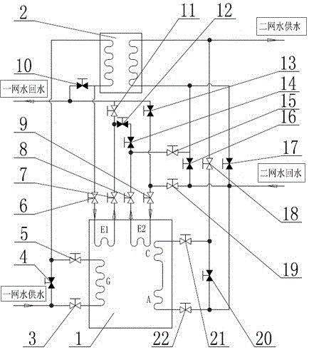
  • Heat pump type large temperature difference heat exchange system and method
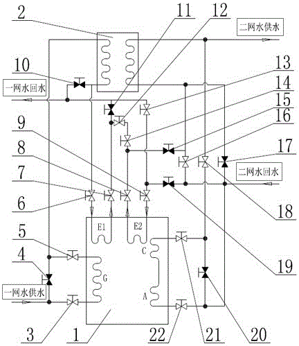
  • Heat pump type large temperature difference heat exchange system and method
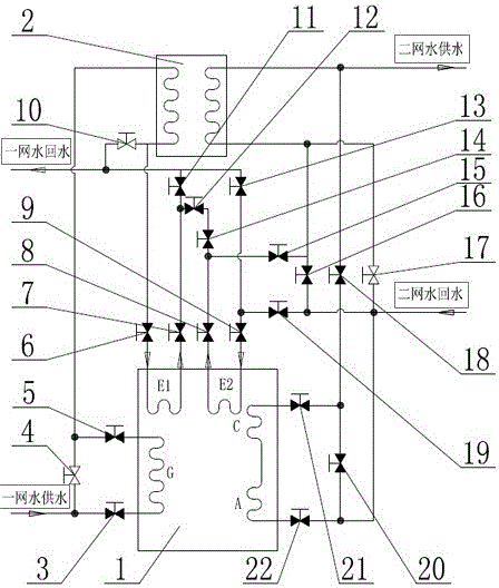
  • Heat pump type large temperature difference heat exchange system and method

Examples


Embodiment 1

[0041] Example 1 (see figure 1 ): a network of high-temperature water as the driving heat source, enters the heat exchange tube of the heat pump / refrigerator (1) generator (G) through the first valve (3) and heats the dilute lithium bromide solution on the outside of the tube until it boils to generate refrigerant Steam and lithium bromide concentrated solution, the high-temperature water in the first network is cooled by the generator (G) and then enters the water-water heat exchanger (2) through the third valve (5) to heat the water in the second network to achieve further cooling. A network of water enters the heat exchange tube of the 1# evaporator (E1) of the heat pump / refrigerator (1) through the fourth valve (6), and is sprayed by the refrigerant water outside the tube, and the refrigerant water evaporates into refrigerant vapor, absorbing The heat of the return water of the first net of water, after releasing heat and cooling down again, the first net of water flows th...

Embodiment 2

[0044] Example 2 (see figure 2 ): a network of high-temperature water as the driving heat source, enters the heat exchange tube of the heat pump / refrigerator (1) generator (G) through the first valve (3) and heats the dilute lithium bromide solution on the outside of the tube until it boils to generate refrigerant Steam and lithium bromide concentrated solution, the high-temperature water in the first network is cooled by the generator (G) and then enters the water-water heat exchanger (2) through the third valve (5) to heat the water in the second network to achieve further cooling. A network of water flows through the fourth valve (6), the heat exchange tube of the 1# evaporator (E1) of the heat pump / refrigerator (1), the fifth valve (7), the tenth valve (12), and the twelfth valve (14), the sixth valve (8) and the heat exchange tube of the 2# evaporator (E2) of the heat pump / refrigerator (1), the 1# evaporator (E1) and the 2# evaporator of the heat pump / refrigerator (1) (...

Embodiment 3

[0048] Example 3 (see Figure 6 ): a network of high-temperature water as the driving heat source, enters the heat exchange tube of the heat pump / refrigerator (1) generator (G) through the first valve (3) and heats the dilute lithium bromide solution on the outside of the tube until it boils to generate refrigerant Steam and lithium bromide concentrated solution, a net of high-temperature water passes through the generator (G) and then enters a secondary water-water heat exchanger (2.2) and a primary water-water heat exchanger ( 2.1), heating the water in the second network to achieve further cooling, the cooled water in the first network enters the heat exchange tube of the heat pump / refrigerator (1) 1# evaporator (E1) through the fourth valve (6), and is cooled by the cooling tube outside the tube The agent water is sprayed, and the refrigerant water evaporates into refrigerant steam, which absorbs the return water heat of a network of water, and after cooling down again, th...


PUM


Abstract

The invention discloses a heat pump type large temperature difference heat exchange system and method. A generator, an absorber, a condenser and evaporators are arranged in a heat pump / refrigerator. The heat pump / refrigerator, water-water heat exchangers, a first-network-water water way and a second-network-water water way are combined and connected through valves and pipelines. The multiple evaporators are arranged. One or more water-water heat exchangers are arranged. When the multiple water-water heat exchangers are arranged, the water-water heat exchangers are connected in series, and the multiple evaporators are connected in series or independently and externally connected. When the multiple evaporators are connected in series, the multiple evaporators, primary parts of the water-water heat exchangers and the generator in the heat pump / refrigerator are connected in the first-network-water water way in series together. When the multiple evaporators are independently and externally connected, the multiple evaporators are connected in the first-network-water water way and the second-network-water water way in series correspondingly. The water supply and return temperature difference of first-network water is enlarged, the heating network conveying capability is improved, due to the low water return temperature of the first-network water, the problems about heat insulation, heat compensation and the like of a water return pipe network can be solved, and the pipe network investment cost and the transmission and distribution energy consumption of the first-network water can be greatly reduced.

Description

technical field [0001] The invention belongs to the technical field of heating engineering, in particular to a heat pump type large temperature difference heat exchange system and method. Background technique [0002] With the continuous expansion of the urban area, the matching heating demand is also increasing. High-temperature hot water often needs to be transported over a long distance to reach the heat exchange station or the location of the heat user. There are problems such as high energy consumption in pipeline transportation and insufficient local heating. increasingly prominent. [0003] For the traditional heat exchanger system, there needs to be a certain heat transfer temperature difference between the first network water and the second network water to achieve effective heat exchange, which theoretically determines that the return water temperature of the first network water should be higher than the return water temperature of the second network water , thus ...

Claims


Application Information

Patent Timeline
IPC IPC(8): F24H4/04F24H9/20F25B41/04F25B15/00F25B41/20
CPCF24H4/04F24H9/2007F25B15/00F25B41/20Y02B30/62Y02A30/27
Inventor 卓志红骆国建陈鹰余健戴子光朱立军杨卫红
Owner HUNAN TOWN ENERGY TECH
Learn More