Open-type cavity prefabricated slab for cast-in-place cavity floor cover

A cavity floor, open technology, applied in the direction of floor slabs, building materials, building components, etc., can solve problems such as slow progress of the project, high construction cost, and affecting the construction speed

Inactive Publication Date: 2016-07-27
HUNAN BDF ENERGY SAVING TECH +2
View PDF15 Cites 1 Cited by
  • Summary
  • Abstract
  • Description
  • Claims
  • Application Information

AI Technical Summary

Problems solved by technology

[0007] The purpose of the present invention is to promote the industrialization process of housing, to improve the existing frame shear wall structure system by using an open cavity prefabricated panel used in cast-in-place cavity floors; The open-cavity prefabricated slab solves the problems of construction, environmental protection, weight, cost, and work efficiency in the existing system; the overall force of the building structure is solved by pouring reinforced concrete on site, combining industrial production of prefabricated floor slabs with on-site pouring The organic combination of reinforced concrete can optimize the existing frame shear wall structure system technology, transform and upgrade the existing prefabricated frame shear wall structure system, and replace it; Strong technicality, on-site construction causes environmental pollution, heavy weight, high construction cost, slow progress of the project, and a large number of building formwork and steel supports are exempted, which leads to long time for formwork and affects the construction speed; the safety caused by the fragile structural parts of steel supports Hidden dangers and difficulty in forming industrialized production

Method used


Image

  • Open-type cavity prefabricated slab for cast-in-place cavity floor cover
  • Open-type cavity prefabricated slab for cast-in-place cavity floor cover
  • Open-type cavity prefabricated slab for cast-in-place cavity floor cover

Examples


Embodiment Construction

[0023] The invention will be further described below in conjunction with the accompanying drawings.

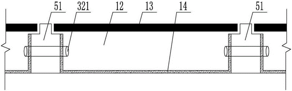
[0024] figure 1It is a plan view of an open cavity prefabricated slab used in the cast-in-situ cavity floor of the present invention. When the present invention is implemented, it is a prefabricated open cavity prefabricated slab 2 that will be produced on the factory assembly line; The bottom formwork system of the type cavity prefabricated slab with a surrounding track is transferred to the formwork workshop and the rib reinforcement and filling body workshop; the bottom formwork is equipped with a vertical formwork to form an open base formwork of the required specification and model, and the open base formwork Install rib beam reinforcement, open mold, willow mold, and through pipes between rib beams, etc.; then transfer the bottom mold system with surrounding rails to the pouring workshop. The computer automatically mixes cement, sand, and stone according to the ratio and...


PUM


Abstract

The invention provides an open-type cavity prefabricated slab for a cast-in-place cavity floor cover. The open-type cavity prefabricated slab comprises a reinforced concrete ribbed beam, an opening mold, a permanent thin cover plate and a reinforced concrete bottom flange plate. At least two reinforced concrete longitudinal ribbed beams and a plurality of reinforced concrete transverse ribbed beams are arranged in the reinforced concrete ribbed beam. The two ends of reinforced bars of the reinforced concrete longitudinal ribbed beams are exposed out. A plurality of reinforced rings are arranged on the upper surface of the reinforced concrete ribbed beam. The upper corner of the reinforced concrete ribbed beam inside the prefabricated slab is a willow angle. The opening mold is a steel mold or a bamboo wood mold or a plastic mold. The geometric dimension of the permanent thin cover plate is larger than that of the caliber of the opening mold. The cross section of a reinforced concrete bottom flange is in an H shape or a T shape. The T-shaped cross section is of a steel mesh concrete structure. The open-type cavity prefabricated slab produced in the process is high in integrity, reasonable in structure, high in quality standard, controllable in working procedure and good in self-insulation and sound-insulation performance.

Description

technical field [0001] The invention relates to a housing industrialization system technology, in particular to an open cavity prefabricated panel technology used in a cast-in-place cavity floor. Background technique [0002] In the 1980s, the production of concrete prefabricated components in my country was in a stage of great development. In the process of housing construction, the country adopted hollow prefabricated slab structures, large slab structures, cast-in-place concrete structures, cast-in-place concrete hollow floor slab structures, and cast-in-place frame shear forces. Wall structure, etc. With the process of housing industrialization, steel-concrete composite structure and steel-concrete composite cavity floor structure system have been developed rapidly. [0003] For example, the ZL98231113.3 concrete thin-walled cylindrical member declared by the applicant is made into a sealed cylindrical filling body, which provides a tubular hollow filling body for the rea...

Claims


Application Information

Patent Timeline
IPC IPC(8): E04B5/36E04C1/00E04B5/48
CPCE04B5/326E04B5/48E04B2103/02E04C1/38
Inventor 王本淼王海崴贾英杰程志军王晓锋
Owner HUNAN BDF ENERGY SAVING TECH
Why Eureka
Try Eureka