
Method and device for converting catalytic cracking cycle oil in classified and divisional manner

A technology for catalytic cracking and circulating oil, which is used in the petroleum industry, processing hydrocarbon oil, hydrocarbon oil processing products, etc., and can solve problems such as lack of effect.

Active Publication Date: 2016-07-27
CHINA UNIV OF PETROLEUM (BEIJING) +1
View PDF5 Cites 7 Cited by
  • Summary
  • Abstract
  • Description
  • Claims
  • Application Information

AI Technical Summary

Problems solved by technology

At the same time, in order to reduce the side reaction (such as hydrogen transfer reaction) of cycloalkane aromatic hydrocarbons into polycyclic aromatic hydrocarbons, the effect after the hydrogenation link is not brought into play. Catalysts with ring cracking ability, such as Y-type molecular sieve catalysts rich in β-cage structure

Method used


Image

  • Method and device for converting catalytic cracking cycle oil in classified and divisional manner
  • Method and device for converting catalytic cracking cycle oil in classified and divisional manner
  • Method and device for converting catalytic cracking cycle oil in classified and divisional manner

Examples


Embodiment 1

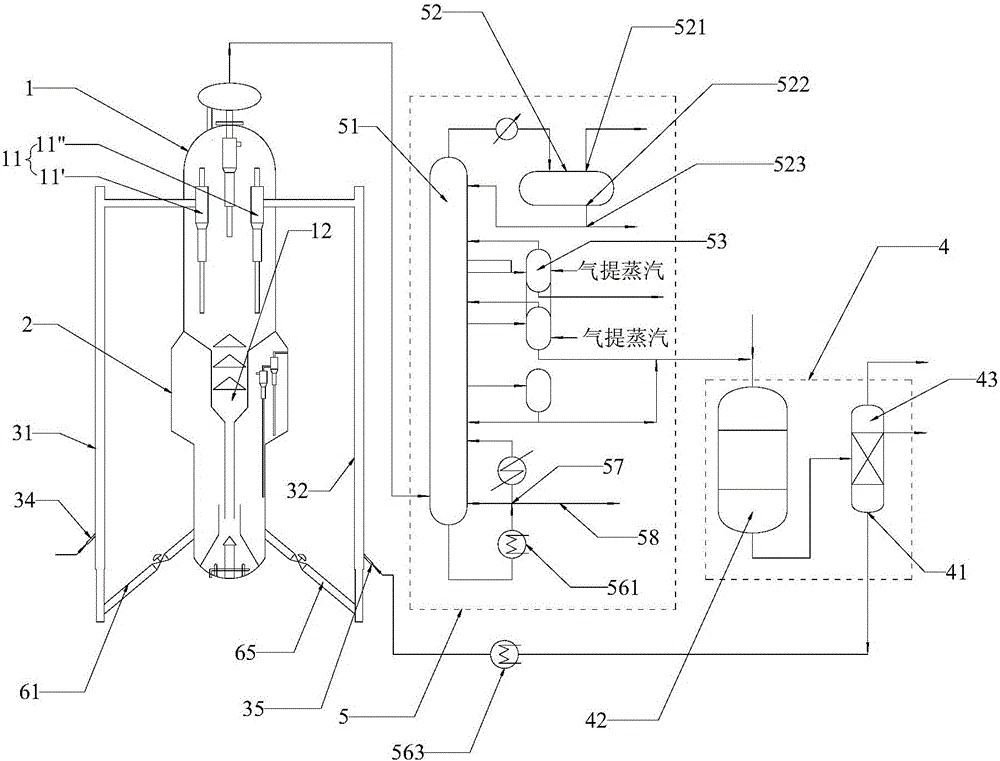
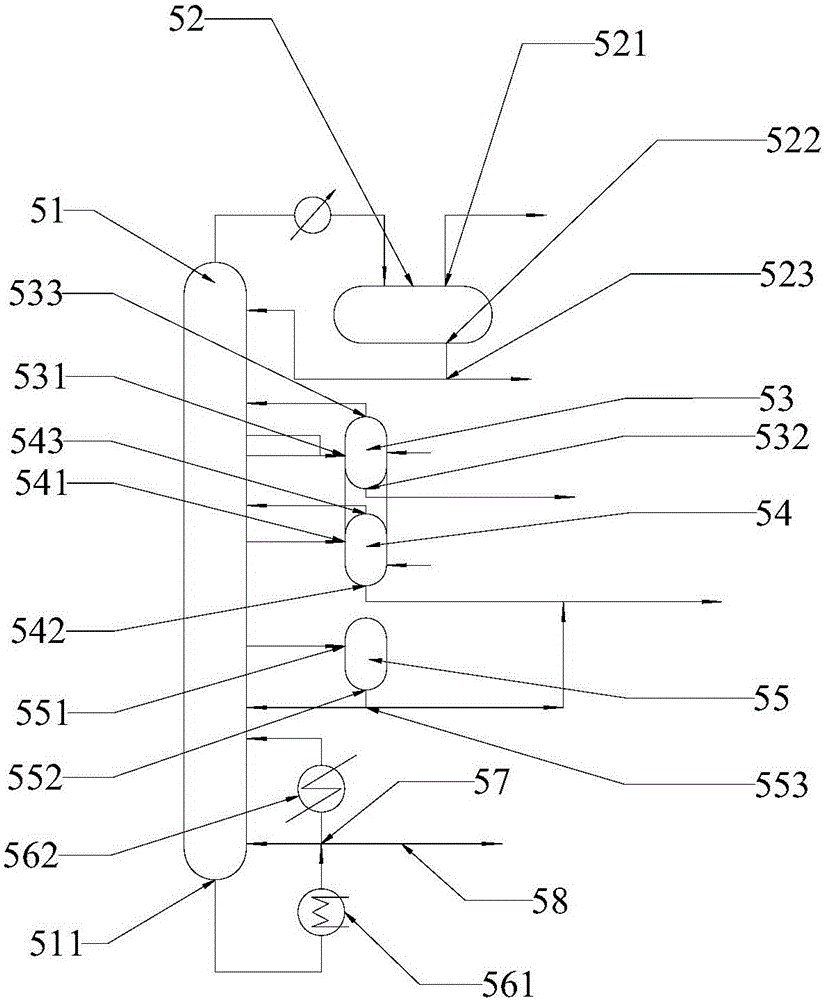
[0059] Device and flow process of the present invention can be seen figure 1 and figure 2 , briefly described as follows: the device includes a settler 1, a regenerator 2, a first riser reactor 31, a second riser reactor 32, a catalytic hydrogenation unit 4 and a fractionation unit 5, wherein the regenerator is arranged at the bottom of the settler , the first riser reactor and the second riser reactor are arranged in parallel, the tops of the two riser reactors are respectively connected to the two gas-solid separation devices 11' and 11" in the settler, and the two riser reactors The bottom is connected to the bottom of the regenerator through the first inclined pipe 61 and the second inclined pipe 62 respectively, the top of the settler is connected to the fractionation unit, and the fractionation unit is connected to the catalytic hydrogenation unit so that the light cycle oil and heavy cycle oil from the fractionation unit are Enter in the catalytic hydrogenation unit a...

Embodiment 2

[0077] Other conditions remain unchanged, using the process conditions in Table 6, the effects shown in Table 7 can be obtained.

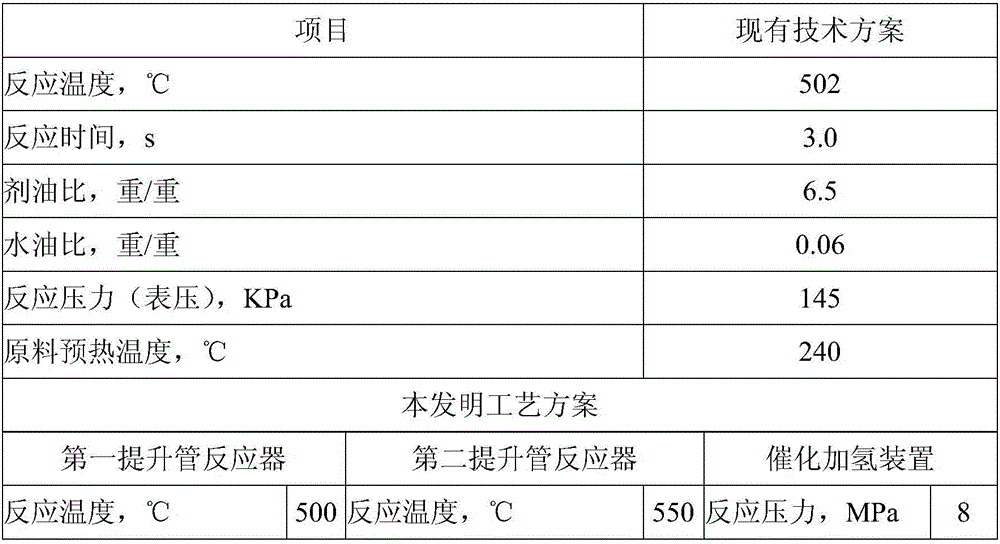
[0078] Table 6 main process conditions

[0079]

[0080]

[0081] Table 7 Distribution of main products

[0082] Product distribution and properties

Embodiment 3

[0084] Other conditions remain unchanged, using the process conditions in Table 8, the effects shown in Table 9 can be obtained.

[0085] Table 8 main process conditions

[0086]

[0087]

[0088] Table 9 Distribution of main products

[0089] Product distribution and properties


PUM


Abstract

The invention provides a method and a device for converting catalytic cracking cycle oil in a classified and divisional manner, wherein the device comprises a settler (1), a regenerator (2), a first riser reactor (31), a second riser reactor (32), a catalytic hydrogenation device (4) and a fractionation device (5); the regenerator is arranged at the bottom of the settler; the first riser reactor and the second riser reactor are arranged in a way of parallel connection; the tops of the two riser reactors are respectively connected with a gas-solid separation device (11) in the settler; the bottoms of the two riser reactors are respectively connected with the bottom of the regenerator by a first inclined tube (61) and a second inclined tube (62); the top of the settler is connected with the fractionation device; the fractionation device is connected with the catalytic hydrogenation device; a raw oil inlet (34) is formed in the first riser reactor (31); a cycle oil inlet (35) is formed in the second riser reactor (32) and is connected with a cycle oil outlet (41) of the catalytic hydrogenation device.

Description

technical field [0001] The invention relates to the field of petroleum product processing, in particular to a method and device for converting catalytic cracking circulating oil in stages and partitions. Background technique [0002] Catalytic cracking cycle oil is an important by-product of catalytic cracking. It is large in quantity and rich in aromatics, especially polycyclic aromatic hydrocarbons. Circulation conversion in catalytic cracking unit. [0003] However, since January 2015, China will implement the National IV emission standard, requiring that the mass fraction of polycyclic aromatic hydrocarbons in vehicle diesel should not exceed 11%, and FCC light cycle oil as a diesel blending component is subject to greater restrictions. Although refining technology has made great progress and innovation in recent years, there is still no better breakthrough in the processing technology of catalytic cracking light cycle oil (LCO), a by-product of refinery with special pr...

Claims


Application Information

Patent Timeline
IPC IPC(8): C10G45/08
CPCC10G45/08C10G2300/1096C10G2400/02
Inventor 王刚常瑞峰孙国峰潘磊
Owner CHINA UNIV OF PETROLEUM (BEIJING)
Learn More