
Design method of isolating switch with disconnection state of contact visible

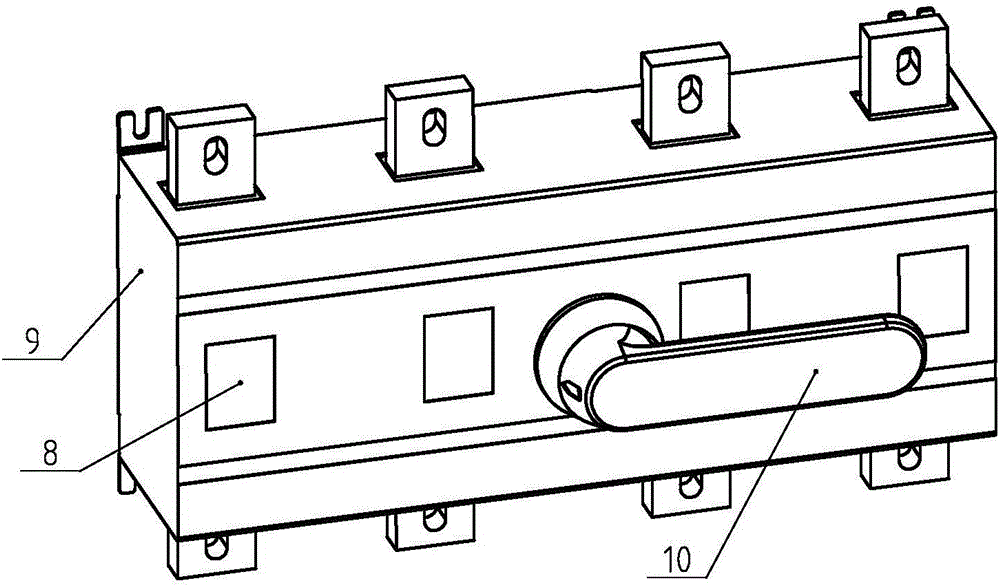
A technology of isolating switch and disconnected state, which is applied in the field of isolating switch design, can solve the problems of increasing the amount of busbar, increasing the manufacturing cost, and increasing the size of the isolating switch, so as to reduce the current density, reduce the consumption, increase the Effect of clearances or safety distances

Inactive Publication Date: 2016-07-20
龚雅丽
View PDF13 Cites 0 Cited by
  • Summary
  • Abstract
  • Description
  • Claims
  • Application Information

AI Technical Summary

Problems solved by technology

And increasing the overlap length will increase the amount of busbars, thereby increasing the manufacturing cost
The fastening bolts will reduce the electrical clearance or safety distance between conductive parts and non-conductive parts. In order to keep the electrical clearance or safety distance unchanged, it is necessary to increase the distance between the terminal and the non-conductive Large spacing will inevitably result in larger dimensions of the entire isolating switch

Method used


Image

  • Design method of isolating switch with disconnection state of contact visible
  • Design method of isolating switch with disconnection state of contact visible
  • Design method of isolating switch with disconnection state of contact visible

Examples


Embodiment 2

[0070] In the first embodiment, the material of the first columnar part 1 is changed to a copper alloy, and the material of the second columnar part 2 is changed to an aluminum alloy. Since the hardness of the alloy is relatively high, the second columnar part 2 can be placed in a low temperature environment ( 5 degrees) for a period of time (5 minutes), while the first columnar part 1 is stored for a period of time (5 minutes) in a high temperature environment (80 degrees), with the help of the effect of thermal expansion and contraction, the inner diameter of the first columnar part 1 Slightly larger, while the outer diameter of the first columnar part 1 is slightly smaller, and then the second columnar part 2 can be easily assembled into the first columnar part 1. After the assembled connecting column returns to normal temperature, the first columnar part 1 Interference fit with the second columnar part 2 can be realized. The diameter and length of the connecting column dis...


PUM


Abstract

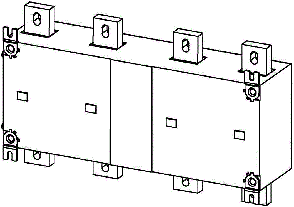
The invention discloses a design method of an isolating switch with a disconnection state of a contact visible, and belongs to the field of electrical equipment. The method comprises the steps that a contact chamber provided with a window for observing connection and disconnection states of a moving contact and a fixed contact, a handle and a connection terminal connected with the fixed contact are provided, a connection column is arranged on the connection terminal, part of the connection column is embedded into the connection terminal and is in interference fit with the connection terminal, a conductive first columnar part which is in interference fit with a power busbar is arranged on the connection column, a conductive second columnar part is coaxially arranged in the first columnar part, the first columnar part is in interference fit with the second columnar part, and the thermal expansion coefficient of the second columnar part is larger than that of the first columnar part. The isolating switch has the following advantages that more conductive areas are produced by the same overlapping length, the electric current density is reduced, and low temperature rise of the connection terminal is achieved; busbar usage is reduced, and resources are saved; electric clearance or safe distance is increased, and the electric safety of the equipment is improved.

Description

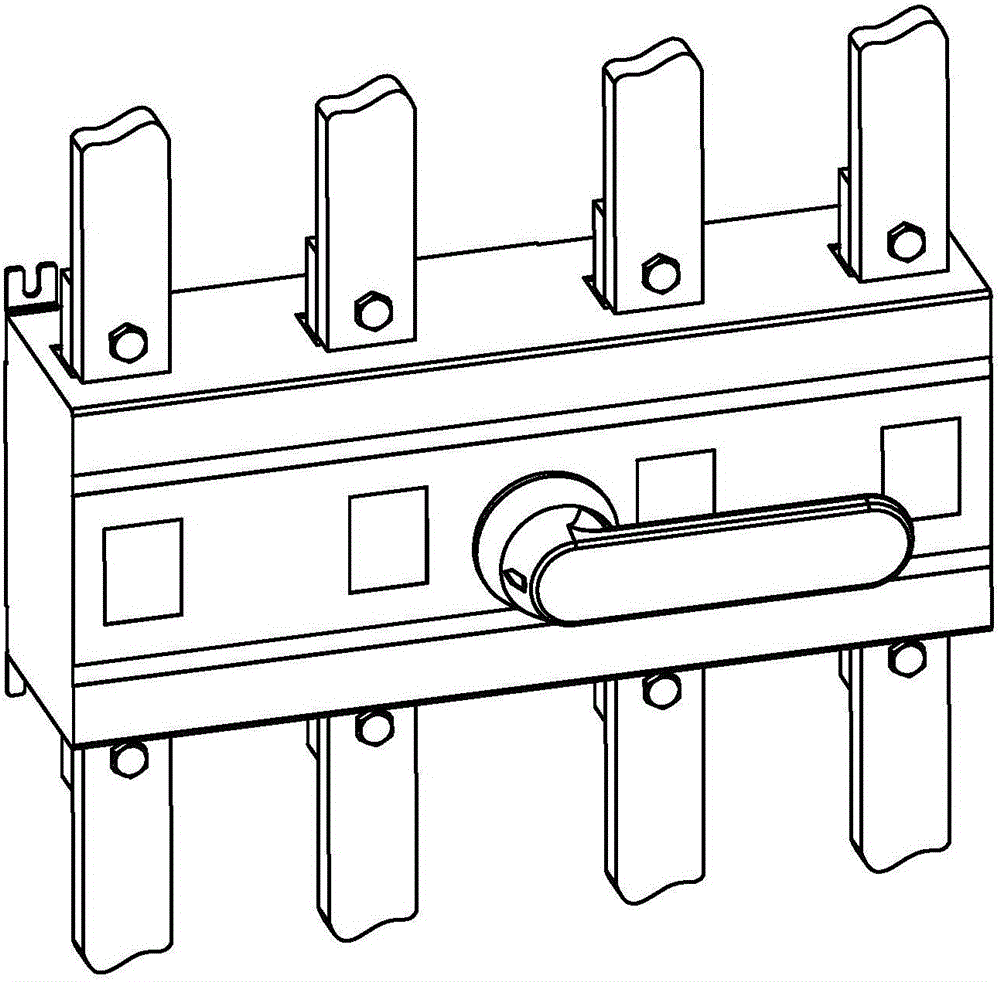
technical field [0001] The invention relates to the field of electric equipment, in particular to a design method of an isolating switch with a visible disconnected state of contacts. Background technique [0002] In the existing power complete equipment factory, construction workers install the isolating switch in the switch cabinet. The terminals of the isolating switch are usually directly connected with the power busbar, and the power busbar is directly connected to the terminal, and the terminal is connected to the power busbar. Usually the overlapping method is used, and then fastened with bolts. Such as image 3 and Figure 4 As shown, this connection method needs to overlap the busbar and the terminal by a certain length, so that the current density of the contact surface can be maintained within a certain range, so that the temperature rise at the connection can meet the relevant standards. In order to reduce the temperature rise at the joint, it is usually necess...

Claims


Application Information

Patent Timeline
IPC IPC(8): H01H1/58H01H9/02
CPCH01H1/58H01H9/02H01H2009/0292
Inventor 不公告发明人
Owner 龚雅丽
Learn More