Experimental area underground water level accurate control system and method
A groundwater level and control system technology, applied in the control/regulation system, liquid level control, non-electric variable control and other directions, can solve the problems of control accuracy and speed need to be improved, and achieve the effect of fast and efficient groundwater level adjustment and easy control
- Summary
- Abstract
- Description
- Claims
- Application Information
AI Technical Summary
Problems solved by technology
Method used
Image
Examples
Embodiment 1
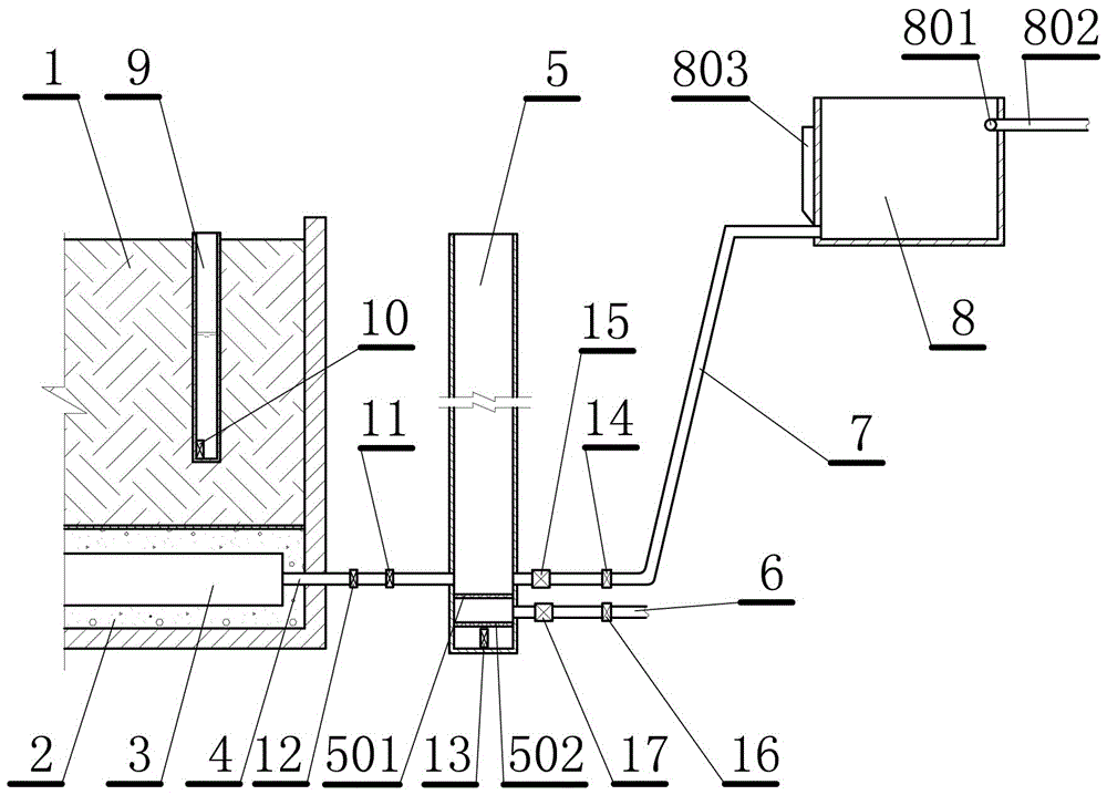
[0025] This embodiment is a precise control system for the groundwater level in the test area, such as figure 1 shown. This embodiment includes: a sand and gravel infiltration layer 2 arranged at the lower part of the original soil layer 1 in the experimental area, and a collection and drainage pipe network 3 arranged horizontally and vertically is buried in the sand and gravel infiltration layer. The connecting pipe 4 is at least connected to a vertically arranged pre-fill drainage well 5, the pre-fill drainage well is connected to the water outlet pipe 6 and the water inlet pipe 7, and the water inlet pipe is connected to the water supply tank 8; the original The soil layer is provided with at least one groundwater level logging well 9; the bottom of the groundwater level logging well is provided with a groundwater level gauge 10, and the connecting pipe is provided with a connecting valve 11 and a drainage pressure gauge 12. The bottom of the filling and drainage well is ...
Embodiment 2
[0059] This embodiment is an improvement of the first embodiment, which is the refinement of the original soil layer and the sand and gravel seepage layer in the first embodiment. At least one layer of filter gauze is arranged between the original soil layer and the gravel infiltration layer described in this embodiment, and the mesh number of the filter gauze is not less than 60 mesh.
[0060] To ensure that the water flow pressure field on the soil surface is similar to the soil in the plain area, a reverse filter gauze is set between the original soil layer and the sand and gravel infiltration layer. The anti-filter gauze can use filter gauze or other filter materials. Considering that the amount of use is very large, the present embodiment selects low-cost filter gauze for use.
Embodiment 3
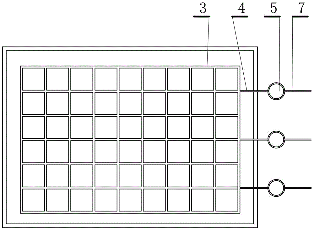
[0062] This embodiment is an improvement of the above embodiment, and is a refinement of the collection and drainage pipe network of the above embodiment. The collection and drainage pipe network described in this embodiment is made of hard plastic or metal pipes, and is in the shape of a grid (such as figure 2 Shown), the pipe wall is evenly distributed with less than 1 mm permeable holes.
[0063] In this embodiment, pipes are vertically staggered and connected, and the distances between the vertically connected parts are equal to form a grid shape, so as to form a uniform inlet and outlet pipe network. Due to the many connected parts of the square grid, the pressure of water in the grid-shaped pipe network is relatively uniform, which can form a uniform water pressure on the soil, and can also quickly and evenly discharge the water in the soil.
PUM
| Property | Measurement | Unit |
|---|---|---|
| Mesh | aaaaa | aaaaa |
| Mesh | aaaaa | aaaaa |
| Permeability coefficient | aaaaa | aaaaa |
Abstract
Description
Claims
Application Information
 - Generate Ideas
- Intellectual Property
- Life Sciences
- Materials
- Tech Scout
- Unparalleled Data Quality
- Higher Quality Content
- 60% Fewer Hallucinations
Browse by: Latest US Patents, China's latest patents, Technical Efficacy Thesaurus, Application Domain, Technology Topic, Popular Technical Reports.
© 2025 PatSnap. All rights reserved.Legal|Privacy policy|Modern Slavery Act Transparency Statement|Sitemap|About US| Contact US: help@patsnap.com


