An automatic inspection machine for smt printing steel mesh

A printing steel mesh and detection machine technology, applied in the direction of tension measurement, measuring devices, instruments, etc., can solve the problems of increasing the cost of the area occupied by the detection device, which is not conducive to popularization and application, and affects the detection accuracy, so as to improve the detection efficiency and accuracy , optimize the load distribution, and improve the effect of detection accuracy

Active Publication Date: 2018-05-29
德中(天津)技术发展股份有限公司
View PDF1 Cites 0 Cited by
  • Summary
  • Abstract
  • Description
  • Claims
  • Application Information

AI Technical Summary

Problems solved by technology

However, the three-coordinate linkage screw device used in this device includes a horizontal axis screw, a vertical axis screw, a vertical axis screw and a slide rail device all driven by a servo motor. The other end is suspended in the air in the shape of a cantilever, and the vertical axis screw and its slide rail device and the working head are installed on the slider of the vertical axis screw. This three-coordinate screw device is due to the horizontal axis screw and its slide rail. It needs to be arranged side by side to support the vertical axis lead screw to keep it horizontal, which increases the floor area of ​​the entire detection device and the cost of the device, which is not conducive to popularization and application
And because the vertical axis screw is in the shape of a cantilever, and both the vertical axis screw and the working head need to move on the vertical axis screw, it is easy to affect the detection accuracy due to the bending of the vertical axis screw
The stencil detection device can only adapt to stencils of the same specification, and its application range is narrow

Method used


Image

  • An automatic inspection machine for smt printing steel mesh
  • An automatic inspection machine for smt printing steel mesh
  • An automatic inspection machine for smt printing steel mesh

Examples


Embodiment Construction

[0023] The present invention will be further described in detail below in conjunction with specific embodiments and accompanying drawings.

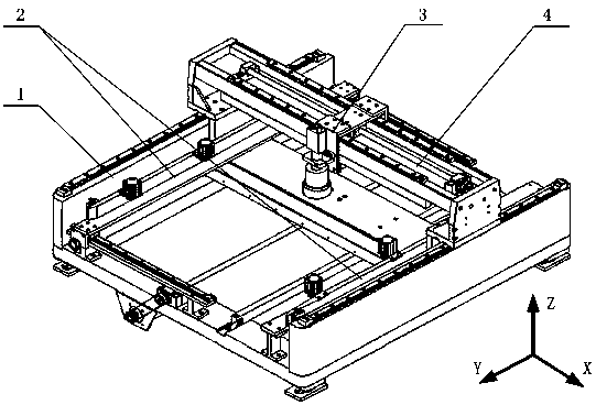
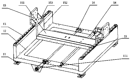
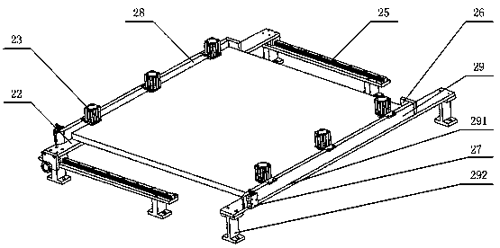
[0024] The SMT printing stencil automatic detection machine (abbreviation detection machine of the present invention's design, see Figure 1-5 ) The overall structure of an embodiment such as figure 1 As shown, the structure of the Y-direction translation mechanism is as follows figure 2 As shown, the structure of the steel mesh support compression mechanism is as follows image 3 As shown, the structure of the tensiometer lifting adjustment assembly (including the tensiometer and the tensiometer connecting plate) is as follows Figure 4 As shown, the structure of the X-direction translation mechanism is as follows Figure 5 shown.

[0025]The detection machine of the present invention is characterized in that the detection machine includes a Y-direction translation mechanism 1, a stencil support and compression mechanism 2, an X-dir...


PUM


Abstract

The invention discloses an automatic detection machine for an SMT printing steel mesh. The detection machine comprises a Y-direction translation mechanism, a steel mesh supporting and pressing mechanism, an X-direction translation mechanism, and a detection mechanism. The X-direction translation mechanism and the Y-direction translation mechanism are in an X axis direction and a Y axis direction, wherein the two directions are perpendicular to each other on a horizontal plane. The Y-direction translation mechanism consists of a shock-absorbing seat, a pedestal, a Y-direction guide rail and a sliding block, a Y-direction sliding table, a bar-shaped light source, a Y-direction grating ruler and a Y-direction lead screw and a nut. The steel mesh supporting and pressing mechanism includes a movable support, a fixed support, a steel mesh support plate, a Y-direction limiting block, a compression cylinder, a steel mesh adjustment guide rail and a slide block thereof. And the X-direction translation mechanism is composed of two X-direction guide rail mounting seats, two X-direction guide rails and a slide block thereof, an X-direction lead screw and a nut, and an X-direction grating ruler. The detection mechanism includes a camera connection plate, a camera, a tensiometer connecting plate, a tensiometer, and a tensiometer lifting regulation element. The detection machine has advantages of high detection precision and wide application range.

Description

technical field [0001] The invention belongs to the field of automatic detection, in particular to an automatic machine for detecting the tension of SMT printing stencils and the position, shape and precision of stencil printing holes. Background technique [0002] SMT (Surface Mount Technology) is the core technology of PCB board assembly and processing. In order to meet the needs of continuous improvement of mounting accuracy and mounting quantity, the requirements of solder paste printing process in SMT processing are becoming increasingly stringent. The quality of SMT printing stencil is the key factor to determine the printing quality. The tension of the stencil and the shape accuracy and position accuracy of the opening of the stencil are important signs for distinguishing the quality of the stencil. [0003] Chinese patent CN201110188321.5 discloses an automatic detection device for printing steel mesh. It adopts a three-coordinate linkage screw device installed on...

Claims


Application Information

Patent Timeline
Patent Type & Authority Patents(China)
IPC IPC(8): G01L5/04G01B11/00G01B11/25G01B11/28
CPCG01B11/00G01B11/2531G01B11/28G01L5/04
Inventor 刘今越任东城刘佳斌郭志红任志斌李洋
Owner 德中(天津)技术发展股份有限公司
Why Eureka
Try Eureka