press machine

A press and driving force technology, applied in the field of presses, can solve the problems of uncertain rotation direction of the driven crankshaft, high cost, complex structure, etc., and achieve the effects of improving start-stop performance, reducing manufacturing cost, and simplifying the structure

Active Publication Date: 2017-11-24
YAMADA DOBBY
View PDF8 Cites 0 Cited by
  • Summary
  • Abstract
  • Description
  • Claims
  • Application Information

AI Technical Summary

Problems solved by technology

[0003] However, in such a transmission structure using a yoke, when the central axis (rotational central axis) of each of the main parts of the plurality of crankshafts and the central axis of the eccentric portion are all located on the same plane, force transmission by the yoke The direction becomes a straight line, so there is a point at which the direction of rotation of the driven crankshaft cannot be determined temporarily, the so-called dead center
Therefore, there is a problem that it is difficult to smoothly transmit the rotational motion among the plurality of crankshafts
[0005] However, in this structure, there is a problem that since many gear parts having a large moment of inertia (inertial force) are used, the moment of inertia based on these gear parts becomes extremely large as a whole of the press machine, and therefore, the Responsiveness at start and stop, so-called start and stop performance of the press is poor
In addition, since the drive force is transmitted from one slider side (drive source) to the other slider side, a link and a plurality of gears are used, so responsiveness (start-stop performance) and synchronization accuracy are poor.
In addition, there is a problem that the rotation amount of the crankshaft and the displacement amount of the slider vary due to the moment of inertia when the press machine is started and stopped, and machining accuracy may deteriorate. Faster forming cycles for presses
[0006] Moreover, in such Patent Document 2, in order to avoid interference between the connecting rods and interference between each connecting rod and the gear (idler gear) or its rotating shaft member, a structure is adopted in which the idler gear is divided into two coaxially rotating parts. Each link is connected to each gear, and the divided idler gears are synchronized with each other through the wide intermediate gear, so the overall structure of the device becomes extremely complicated.
In addition, there is a problem that, in addition to the large number of components, the accuracy and clearance of each gear need to be adjusted in order to drive the left and right sliders synchronously, and therefore the cost of the entire device increases due to the countermeasures.

Method used


Image

  • press machine
  • press machine
  • press machine

Examples


Embodiment Construction

[0057] Hereinafter, in order to clarify the present invention more concretely, embodiments of the present invention will be described in detail with reference to the drawings.

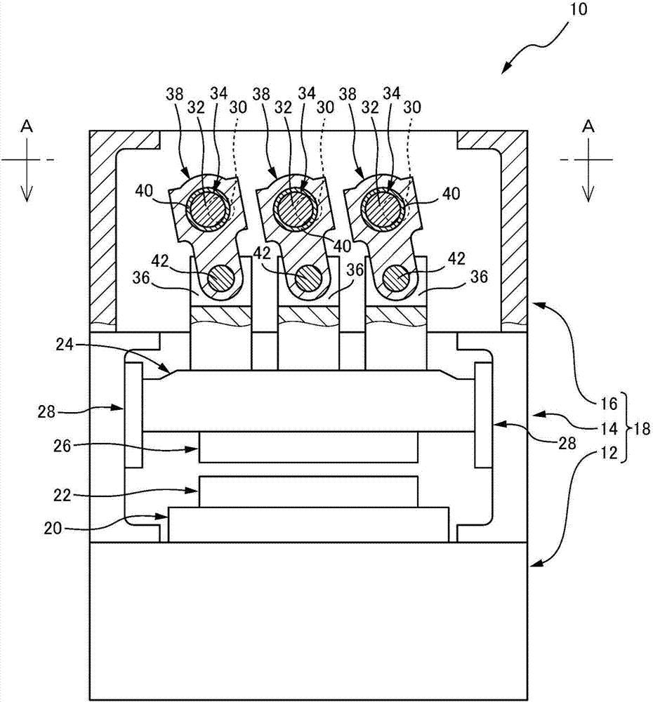
[0058] first, figure 1 An example of a press according to the present invention is shown in a front view including a part in section. Here, the press machine 10 is provided with a frame body 18 of an integral structure composed of a lower frame body 12 , an intermediate frame body 14 , and an upper frame body 16 . The lower die 22 is attached, and an upper die 26 constituting a press die together with the lower die 22 is attached to the lower surface of the slider 24 arranged in the intermediate frame 14 . In addition, the slider 24 is arranged in a vertically movable state guided by a pair of slider guides 28 , 28 provided to face the inner wall surface of the intermediate housing 14 . In addition, as will be described later, the upper housing 16 is rotatably supported by a plurality of (here, three...


PUM


Abstract

The present invention provides a press machine having an improved structure capable of smoothly transmitting rotational drive force between a plurality of crankshafts, and also capable of improving the start-stop performance of the press machine and realizing machining accuracy Improvement, and can achieve high-speed molding cycle. In the press machine (10), a first connecting rod (48) for synchronously rotating a plurality of crankshafts (34, 34, 34) having a main shaft part (30) and an eccentric shaft part (32) is configured. , 48) are respectively installed on each eccentric shaft part (32, 32, 32), on the other hand, the second connecting rod (56) is respectively installed on each pin (54, 54, 54), and the pin is connected with the eccentric shaft part (32) The crankshafts (34, 34, 34) are integrally provided at different circumferential positions with respect to the main shaft portion (30).

Description

technical field [0001] The present invention relates to a press machine, and more particularly, to a press machine having an improved configuration enabling smooth transmission between crankshafts of a plurality of crankshafts that drive a slide for mounting a stamping die Rotational driving force. Background technique [0002] Conventionally, as a press machine driven by a crankshaft, a press machine is known in which a plurality of crankshafts are synchronously rotated to reciprocate a slider attached to a press die. In addition, as one of such presses, the applicant of the present application previously clarified in Japanese Unexamined Patent Application Publication No. 9-155595 (Patent Document 1) a press machine in which one of a plurality of crankshafts is connected to each other by using a yoke. The rotational motion of at least one crankshaft is transmitted to the other crankshafts. Therefore, the rotational movement of the crankshaft driven to rotate (drive cranks...

Claims


Application Information

Patent Timeline
Patent Type & Authority Patents(China)
IPC IPC(8): B30B1/14B30B15/14
CPCB30B1/266B30B1/26
Inventor 吉田晶洋服部龙一
Owner YAMADA DOBBY
Why Eureka
Try Eureka