Metal powder injection-molding sintering jig

An injection molding and metal powder technology, which is applied in the field of metal powder injection molding and sintering fixtures, can solve the problems of easy product deformation, low blank sintering production efficiency, and high scrap rate, and is conducive to on-site management, simple structure, and improved The effect of production efficiency

Inactive Publication Date: 2016-07-20
KUNSHAN AT & MIK METAL MATERIALS CO LTD
View PDF6 Cites 2 Cited by
  • Summary
  • Abstract
  • Description
  • Claims
  • Application Information

AI Technical Summary

Problems solved by technology

[0003] The purpose of this invention is to propose a metal powder injection molding sintering fixture to solve the problems of low sintering production efficiency of blanks, easy deformation of products, and high scrap rate

Method used


Image

  • Metal powder injection-molding sintering jig
  • Metal powder injection-molding sintering jig

Examples


Embodiment Construction

[0019] In order to make the technical problems solved by the present invention, the technical solutions adopted and the technical effects achieved clearer, the technical solutions of the embodiments of the present invention will be further described in detail below in conjunction with the accompanying drawings. Obviously, the described embodiments are only the technical solutions of the present invention. Some, but not all, embodiments. Based on the embodiments of the present invention, all other embodiments obtained by those skilled in the art without creative efforts fall within the protection scope of the present invention.

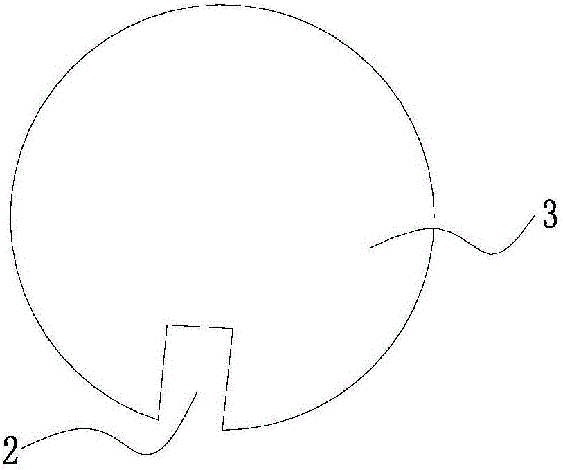
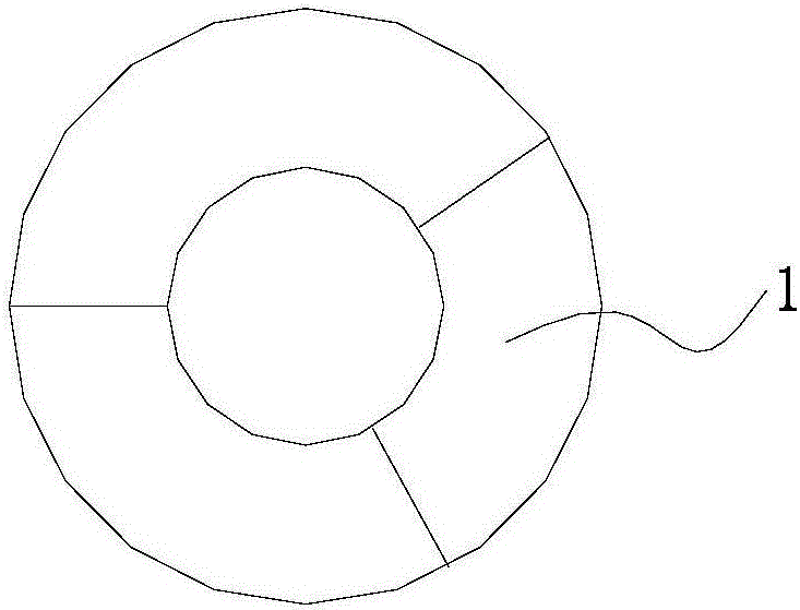
[0020] Such as figure 1 and figure 2 As shown, this embodiment proposes a preferred metal powder injection molding sintering fixture, which includes a fixture body, the fixture body has a support platform for supporting the workpiece 1 to be sintered, and the fixture body is provided with The positioning groove 2 is used for fixing the workpiece 1 t...


PUM


Abstract

The invention discloses a metal powder injection-molding sintering jig, and relates to the technical field of sintering jigs. The metal powder injection-molding sintering jig comprises a jig body. The jig body comprises a supporting platform used for supporting a to-be-sintered workpiece. A positioning groove is formed in the jig body and used for fixing the to-be-sintered workpiece. The metal powder injection-molding sintering jig is simple in structure and capable of effectively preventing sintering deformation of a metal powder injection-molded product, the workpiece placement work can be easy, the production efficiency is improved, product storage can be neater, and field management is better facilitated.

Description

technical field [0001] The invention relates to the technical field of sintering fixtures, in particular to a metal powder injection molding sintering fixture. Background technique [0002] Metal powder injection molding technology is a new manufacturing process technology that combines powder metallurgy and plastic molding technology. It is required to first mix the selected powder with a binder, and then granulate the mixture before injection molding. shape. After molding, remove the binder, and then sinter the degreased body. However, the product is very fragile before sintering, especially after the binder is removed, especially for irregularly shaped blanks, which are prone to fracture, bending, displacement and other deformations, resulting in scrapping of the product; and when the blank When the quantity is large, the sintering needs to be placed in a fixed posture, which requires a lot of manpower to correctly place the products one by one, and the production effic...

Claims


Application Information

Patent Timeline
Patent Type & Authority Applications(China)
IPC IPC(8): B22F3/22B22F3/10
CPCB22F3/225B22F3/10B22F2003/1042
Inventor 何建久祁新亮陈璟文孟坤全王传兴崔晓波
Owner KUNSHAN AT & MIK METAL MATERIALS CO LTD
Why Eureka
Try Eureka