Method and device for integrated removal of multi-pollutants in tail gas by plant ash slurry
A technology for plant ash and pollutants, applied in chemical instruments and methods, separation methods, gas treatment, etc., can solve problems such as solid waste generation, limited secondary utilization channels, and endangering the health of the ecological environment
- Summary
- Abstract
- Description
- Claims
- Application Information
AI Technical Summary
Problems solved by technology
Method used
Image
Examples
Embodiment 1
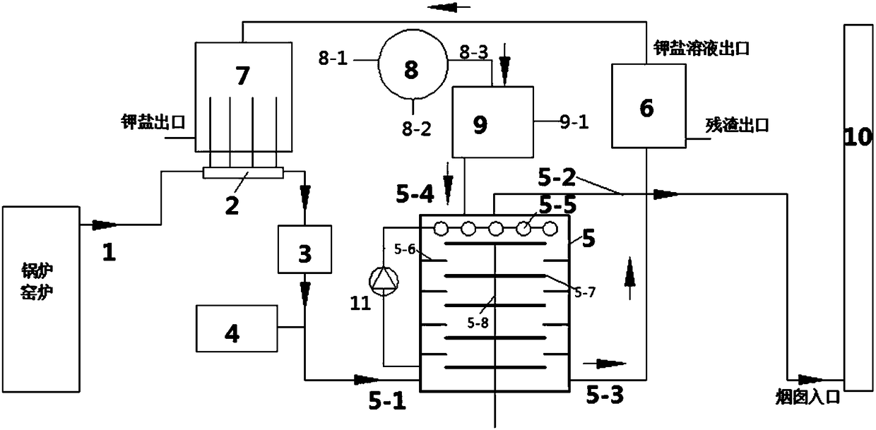
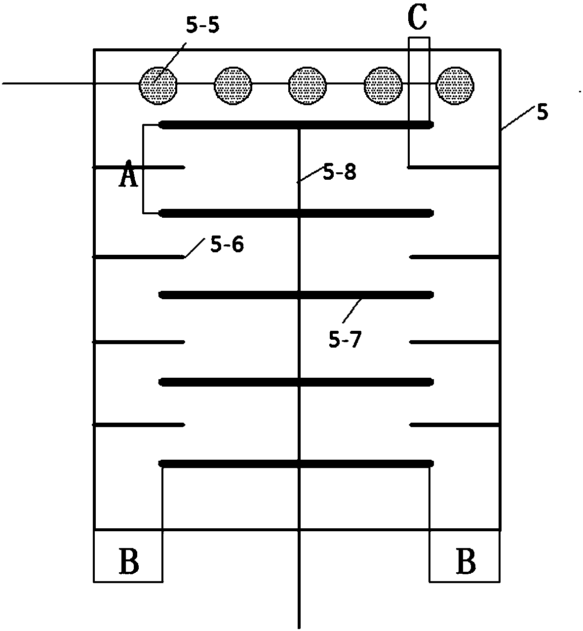
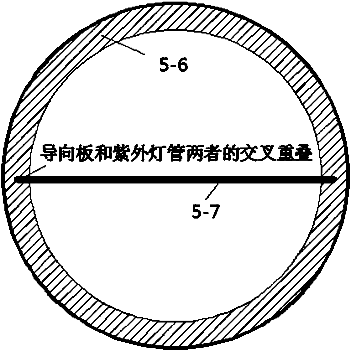
[0068] Example 1. SO in flue gas 2 , NO x , Hg, H 2 The concentrations of S, HCl, and HF are respectively 5000ppm, 500ppm, and 80ug / m 3 , 3000ppm, 1000ppm and 1000ppm, flue gas temperature is 45°C, liquid-gas ratio is 5L / m 3 , the mass concentration of plant ash slurry is 100g / L, and the longitudinal distance A between the ultraviolet lamp tubes is located at 10cm. The distance B between the top of the ultraviolet lamp tube and the reactor wall is 1 cm, and the overlapping length of the ultraviolet lamp tube and the guide plate is between 2 cm. The guide plate is arranged at the center of the longitudinal distance between two adjacent ultraviolet lamp tubes. The solution atomization diameter of the nozzle is 150 microns. The rotation speed of the rotating paddle is 20 rpm. SO in flue gas 2 , NO x , Hg, H 2 The simultaneous removal efficiencies of S, HCl and HF were 59.3%, 15.9%, 28.9%, 48.8%, 58.8% and 48.2%, respectively.
Embodiment 2
[0069] Example 2. SO in flue gas 2 , NO x , Hg, H 2 The concentrations of S, HCl, and HF are respectively 5000ppm, 500ppm, and 80ug / m 3 , 3000ppm, 1000ppm and 1000ppm, flue gas temperature is 45°C, liquid-gas ratio is 8L / m 3 , the mass concentration of plant ash slurry is 100g / L, and the longitudinal distance A between the ultraviolet lamp tubes is located at 10cm. The distance B between the top of the ultraviolet lamp tube and the reactor wall is 1 cm, and the overlapping length of the ultraviolet lamp tube and the guide plate is between 2 cm. The guide plate is arranged at the center of the longitudinal distance between two adjacent ultraviolet lamp tubes. The solution atomization diameter of the nozzle is 150 microns. The rotation speed of the rotating paddle is 20 rpm. SO in flue gas 2 , NO x , Hg, H 2 The simultaneous removal efficiencies of S, HCl and HF were 78.3%, 24.9%, 30.9%, 69.3%, 78.8% and 68.7%, respectively.
Embodiment 3
[0070] Example 3. SO in flue gas 2 , NO x , Hg, H 2 The concentrations of S, HCl, and HF are respectively 5000ppm, 500ppm, and 80ug / m 3 , 3000ppm, 1000ppm and 1000ppm, the flue gas temperature is 45°C, the molar concentration of hydrogen peroxide is 0.08mol / L, the ozone injection concentration is 30ppm, and the liquid-gas ratio is 5L / m 3 , the mass concentration of plant ash slurry is 100g / L, and the longitudinal distance A between the ultraviolet lamp tubes is located at 10cm. The distance B between the top of the ultraviolet lamp tube and the reactor wall is 1 cm, and the overlapping length of the ultraviolet lamp tube and the guide plate is between 2 cm. The guide plate is arranged at the center of the longitudinal distance between two adjacent ultraviolet lamp tubes. The solution atomization diameter of the nozzle is 150 microns. The rotation speed of the rotating paddle is 20 rpm. SO in flue gas 2 , NO x , Hg, H 2 The simultaneous removal efficiencies of S, HCl a...
PUM
 Abstract
Description
Claims
Application Information
 - R&D
- Intellectual Property
- Life Sciences
- Materials
- Tech Scout
- Unparalleled Data Quality
- Higher Quality Content
- 60% Fewer Hallucinations
Browse by: Latest US Patents, China's latest patents, Technical Efficacy Thesaurus, Application Domain, Technology Topic, Popular Technical Reports.
© 2025 PatSnap. All rights reserved.Legal|Privacy policy|Modern Slavery Act Transparency Statement|Sitemap|About US| Contact US: help@patsnap.com


