


Quick Research
Generate reliable direction feasibility study reports for your R&D in just a few steps.

Technical Q&A
Discover and master advanced knowledge NOW. Basics, ideas, possibilities, all at once.

Find Solutions
As an expert in R&D theories, this can generate solutions to your technical problems instantly.

Evaluate Feasibility
Analyze your overall solution with one click, know your potential R&D risks in advance.

Monitor Landscape
Get weekly tech updates, stay abreast of the latest tech innovations and key insights.
Method for producing pneumatic tire
A technology for a pneumatic tire and a manufacturing method, which is applied to pneumatic tires, tire parts, and the absence of a separate inflatable pad, etc., can solve the problems of damage to the inner liner, heavy labor, and difficulty in removing the mold release agent, so as to inhibit peeling. , The effect of preventing the decrease of adhesion
- Summary
- Abstract
- Description
- Claims
- Application Information
AI Technical Summary
Problems solved by technology
Method used
Image

Examples
Embodiment 1
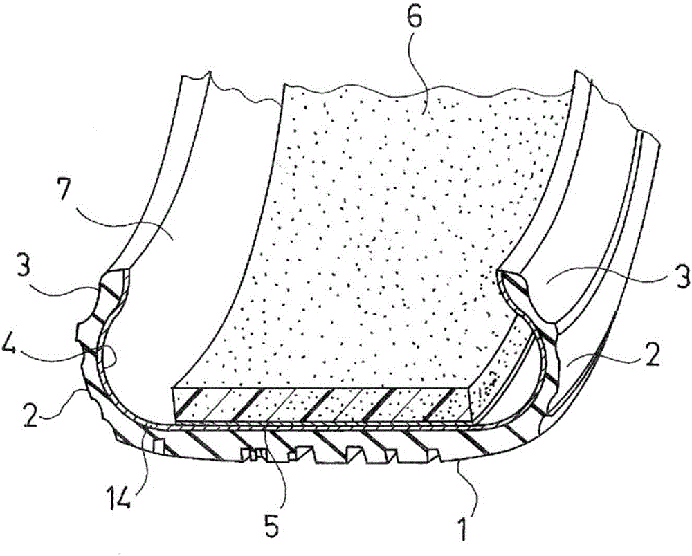
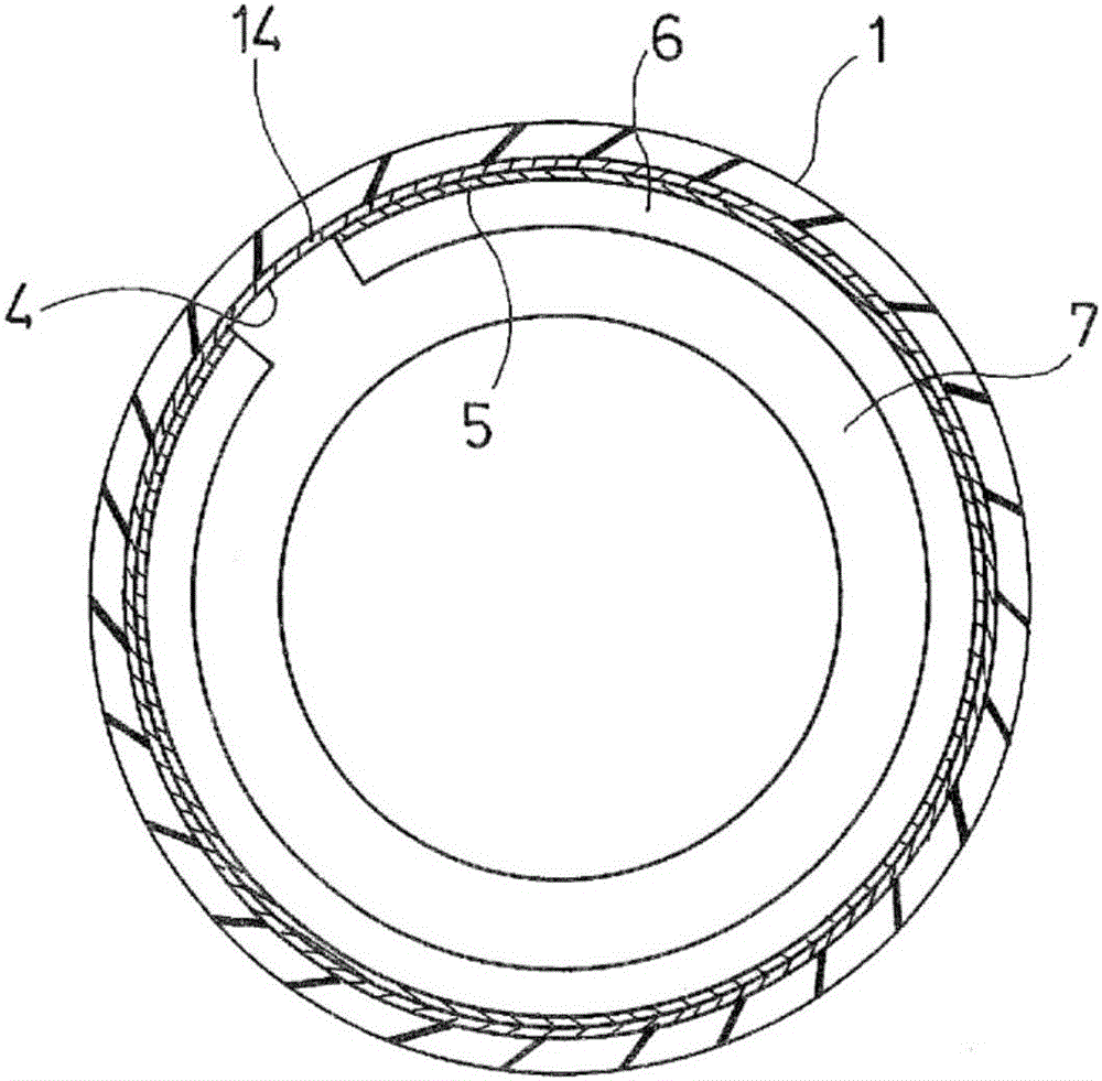
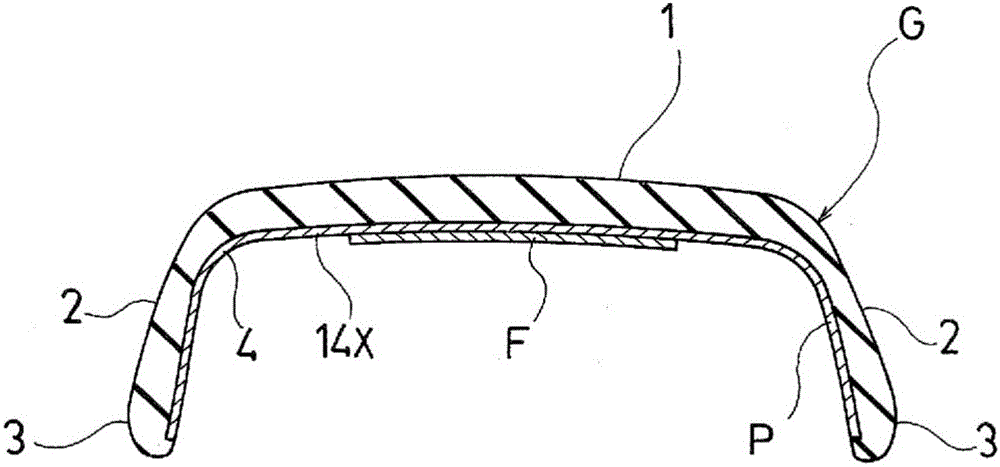
[0062] In Examples 1, 6, and 7, a green tire provided with an inner liner member was molded, and a film was attached to the region corresponding to the tread portion of the inner surface of the green tire by the adhesive force of the inner liner member. A release agent is applied to the inner surface of a raw tire having the film, the green tire coated with the release agent is vulcanized, and the film is removed from the inner surface of the pneumatic tire obtained by the vulcanization process, and after peeling off the film On the exposed area, a strip-shaped sound-absorbing material is adhered along the tire circumferential direction by means of an adhesive layer. In Example 1, the polymer constituting the film was nylon 6 monomer (N6), and its thickness was 50 μm. In Example 6, the polymer constituting the film was polyethylene terephthalate monomer (PET), and its thickness was 50 μm. In Example 7, the polymer constituting the film was nylon 66 monomer (N66), and its thic...
Embodiment 5
[0064] In Example 5, a thin film is attached to a region corresponding to the tread portion of a sheet-shaped inner liner member by the adhesive force of the inner liner member, and the film is placed on the inner surface of the tire and laminated to form an inner liner. member, and then mold a green tire including the inner liner member, apply a release agent on the inner surface of the green tire with the film, vulcanize the green tire coated with the release agent, and then proceed through the vulcanization process The film was removed from the inner surface of the obtained pneumatic tire, and a strip-shaped sound-absorbing material was bonded along the tire circumferential direction via an adhesive layer on the exposed area after peeling off the film. In Example 5, the polymer constituting the film was nylon 6 monomer (N6), and its thickness was 50 μm.
[0065] Here, in Examples 1 to 7, the cutting angle of the film at both end portions in the tire circumferential directio...
PUM
| Property | Measurement | Unit |
|---|---|---|
| thickness | aaaaa | aaaaa |
| hardness | aaaaa | aaaaa |
| tensile strength | aaaaa | aaaaa |
Abstract
Description
Claims
Application Information
 - R&D Engineer
- R&D Manager
- IP Professional
- Industry Leading Data Capabilities
- Powerful AI technology
- Patent DNA Extraction
Browse by: Latest US Patents, China's latest patents, Technical Efficacy Thesaurus, Application Domain, Technology Topic, Popular Technical Reports.
© 2024 PatSnap. All rights reserved.Legal|Privacy policy|Modern Slavery Act Transparency Statement|Sitemap|About US| Contact US: help@patsnap.com