
High-back pressure combined heat and power generation system coupled with exhaust steam and supply heat of non-reheat steam turbine

A technology for cogeneration and steam turbines, which is applied in steam engine installations, energy industry, mechanical equipment, etc., can solve complex heating needs and other problems, and achieve the effects of improving heating comfort, reducing heat exchange temperature difference, and reducing heat exchange loss.

Inactive Publication Date: 2016-07-06
NORTH CHINA ELECTRIC POWER UNIV (BAODING)
View PDF4 Cites 11 Cited by
  • Summary
  • Abstract
  • Description
  • Claims
  • Application Information

AI Technical Summary

Problems solved by technology

[0008] The purpose of the present invention is to provide a high back pressure cogeneration system coupled with exhaust heat supply of a non-reheat steam turbine to solve the complex heat supply demand mentioned in the background technology and reduce the impact of heat supply on the power generation of the unit and other issues, so that under the premise of ensuring the heating comfort of heat users, the power generation capacity is relatively high, and the deep energy saving of the combined heat and power system can be achieved.

Method used


Image

  • High-back pressure combined heat and power generation system coupled with exhaust steam and supply heat of non-reheat steam turbine

Examples


Embodiment Construction

[0030] The present invention will be further described below in conjunction with the accompanying drawings and embodiments.

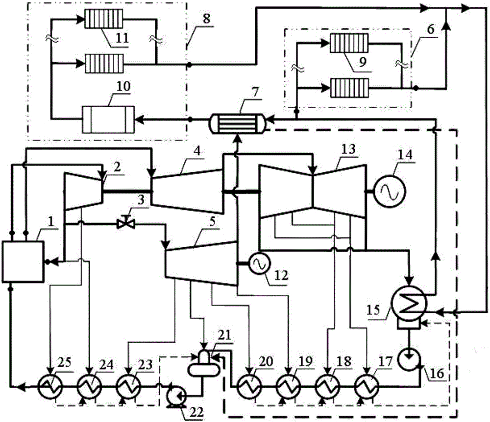
[0031] figure 1 The high back pressure cogeneration system coupled with the exhaust heat supply of the non-reheat steam turbine is composed of the power generation system side and the heat supply system side; On the power generation system side, the turbogenerator set includes generator I14, high-pressure cylinder 2, medium-pressure cylinder 4, low-pressure cylinder 13, generator II12 and non-reheat medium-pressure steam turbine 5, generator I14 and high-pressure cylinder 2, medium-pressure steam turbine of the main steam turbine The pressure cylinder 4 and the low-pressure cylinder 13 are arranged coaxially, and the generator II 12 is arranged coaxially with the added non-reheat medium-pressure steam turbine 5 . The shaft of generator I14 is connected to the shaft of low-pressure cylinder 13, the shaft of low-pressure cylinder 13 is connected to the s...


PUM


Abstract

The invention belongs to the technical field of thermoelectricity, and relates to a high back pressure heat and power cogeneration system coupled with exhaust steam heat supply of a non-reheat steam turbine. A non-reheat medium-pressure steam turbine and generator II are added to the power generation system, and the heating system mainly includes a high backpressure heating condenser, a non-reheat medium-pressure steam turbine, a heat network heater, a remote heat network and a short-range heat network. The exhaust steam from the low-pressure cylinder of the main steam turbine enters the heating condenser to condense and release heat. The circulating water in the condenser absorbs heat and enters the short-distance heating network or heating network heater. The exhaust steam from the steam turbine is further heated and enters the remote heating network, and the return water from the remote and short-range heating networks is mixed and then enters the condenser. The invention utilizes the waste heat of the exhaust steam of the steam turbine to reduce the loss of the cooling source; the return water of the short-range and remote heating network is mixed, so that the temperature of the return water of the heating network entering the condenser is reduced, and the utilization efficiency of waste heat is improved. The invention is suitable for the heat supply transformation of 300MW and above large-capacity units with short-range low-temperature heat demand.

Description

technical field [0001] The invention belongs to the technical field of thermoelectricity, and in particular relates to a high back pressure combined heat and power system coupled with exhaust steam heat supply of a non-reheat steam turbine. Background technique [0002] Thermal power to improve energy conversion efficiency, realize efficient energy utilization and integrated control of pollutants is an important way to achieve energy conservation and emission reduction of fossil energy such as coal, and cogeneration of heat and power is one of the important measures. The combined heat and power unit supplies heat to the outside while generating electricity, which can effectively reduce the loss of cold sources. Using cogeneration technology, the comprehensive utilization efficiency of thermal power energy can theoretically be increased to more than 80%. [0003] Under the existing technology, the standard coal consumption of centralized heating with combined heat and power ...

Claims


Application Information

Patent Timeline
Patent Type & Authority Applications(China)
IPC IPC(8): F01D13/02F01D15/10F01D25/30F01D25/32F01K7/16F01K17/02
CPCY02E20/14Y02P80/15F01D13/02F01D15/10F01D25/30F01D25/32F01K7/16F01K17/02
Inventor 杨勇平赵世飞孙诗梦戈志华何坚忍
Owner NORTH CHINA ELECTRIC POWER UNIV (BAODING)
Learn More