Fabricated double-layer steel plate swinging wall with ductility energy consumption connecting pieces
A technology for connecting parts and swinging walls, which is applied in the directions of walls, building components, and anti-vibration, can solve the problems of insufficient rocking performance of the swinging wall structure, unreasonable connection form of the main structure, and inconvenient on-site construction, and achieves high rigidity and construction speed. The effect of fast, reducing the likelihood of serious damage
- Summary
- Abstract
- Description
- Claims
- Application Information
AI Technical Summary
Problems solved by technology
Method used
Image
Examples
Embodiment 1
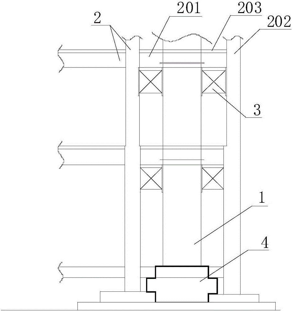
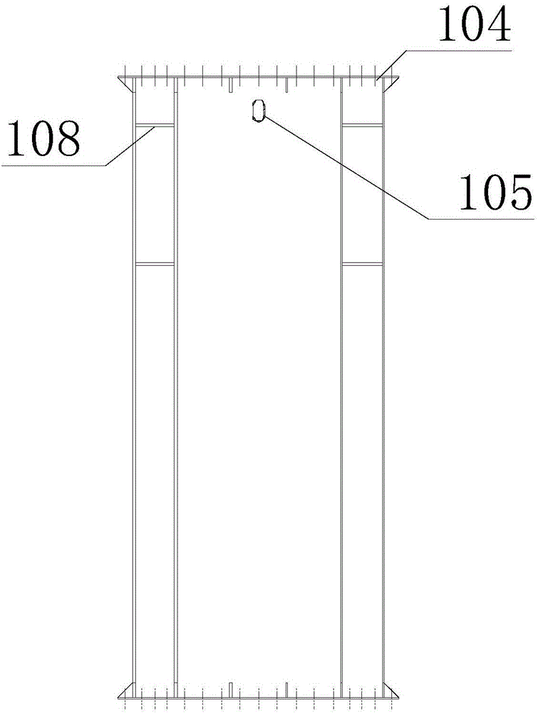
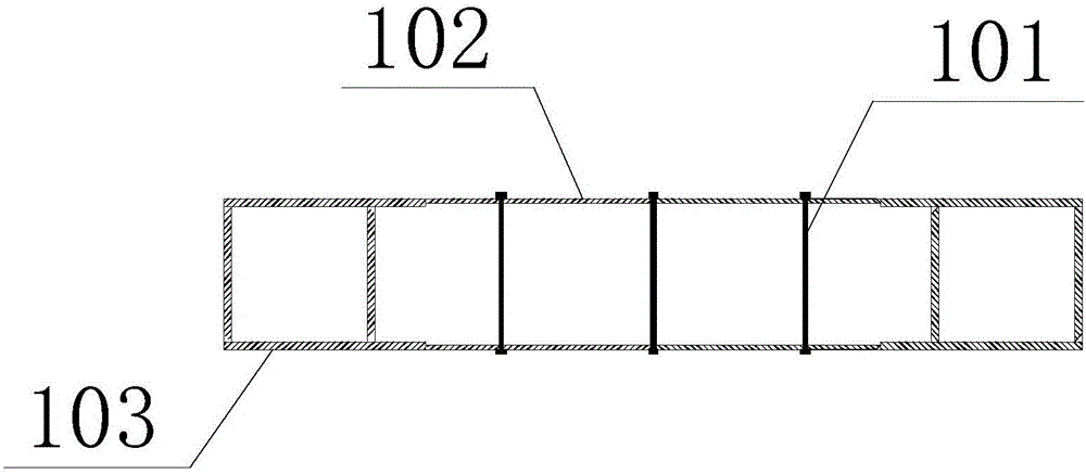
[0035] This embodiment consists of a double-layer steel plate wall 1, a main frame structure 2, a ductile energy-dissipating connector 3, a hinge support 4 at the bottom of the wall, and a flexible filling material 6. During construction, first pour the hinge support 4 at the bottom of the wall, such as Figure 4 As shown, the hinge support 4 at the bottom of the wall is made of reinforced concrete into a groove shape, the width is the same as the thickness of the double-layer steel plate wall 1, the length of the bottom of the groove is the same as the length of the bottom end of the double-layer steel plate wall 1, and the edge of the groove is at a certain angle with the horizontal plane. The steel plate in the tank is used as the contact surface, and the steel plate and the reinforced concrete part are anchored by bolts, and the concrete is vibrated and compacted after pouring.
[0036] The double-layer steel plate wall 1 is a prefabricated component, such as figure 2 As...
Embodiment 2
[0040] Figure 5 It is the elevation schematic diagram of the double-layer steel plate wall part in this embodiment. For the prefabricated double-layer steel plate swing wall assembly with ductile energy-dissipating connectors arranged at the position where the distance between the frame columns 202 is relatively large, it can be as follows Figure 5 and Figure 6 As shown, the outrigger connection 5 is set, and the strengthening member is set in the wall.
[0041] One end of the outrigger connection 5 is welded to the double-layer steel plate wall 1, and the other end is welded to 303 and connected to the ductile energy-dissipating connector 3; the flange plate of the outrigger connection 5 is gradually widened near the double-layer swinging wall 1, And extend into the double-layer steel plate wall 1 inside.
[0042] The edge-constrained square steel pipe of the double-layer steel plate wall 1 is provided with a transverse diaphragm 108 with a round hole at the position of...
PUM
 Abstract
Description
Claims
Application Information
 - R&D
- Intellectual Property
- Life Sciences
- Materials
- Tech Scout
- Unparalleled Data Quality
- Higher Quality Content
- 60% Fewer Hallucinations
Browse by: Latest US Patents, China's latest patents, Technical Efficacy Thesaurus, Application Domain, Technology Topic, Popular Technical Reports.
© 2025 PatSnap. All rights reserved.Legal|Privacy policy|Modern Slavery Act Transparency Statement|Sitemap|About US| Contact US: help@patsnap.com


