
Reinforcement structure for inclined cracks in main girder web plate of box girder bridge and construction method thereof

A main girder web, reinforcement structure technology, applied in the direction of bridge reinforcement, bridge, bridge maintenance, etc., can solve the problems of difficult to ensure the effect of stress application, difficult to effectively measure the tensile force, unable to replace, etc., to achieve the replacement of external vertical prestress The effect of convenient reinforcement, simple method and convenient reinforcement structure

Active Publication Date: 2016-07-06
广州展亚土木工程技术有限公司
View PDF7 Cites 9 Cited by
  • Summary
  • Abstract
  • Description
  • Claims
  • Application Information

AI Technical Summary

Problems solved by technology

[0005] (1) The vertical prestressed steel bars in the body are stretched by tightening the end nuts. After tensioning, the tension generated in the vertical prestressed steel bars in the body is difficult to effectively measure, and it is difficult to ensure the effect of stress application
[0006] (2) If the vertical prestressed reinforcement in the body needs to be replaced during the operation period, it cannot be replaced because the channels of the vertical prestressed reinforcement in the body have been grouted

Method used


Image

  • Reinforcement structure for inclined cracks in main girder web plate of box girder bridge and construction method thereof
  • Reinforcement structure for inclined cracks in main girder web plate of box girder bridge and construction method thereof
  • Reinforcement structure for inclined cracks in main girder web plate of box girder bridge and construction method thereof

Examples


Embodiment Construction

[0042] The present invention will be further described below in conjunction with drawings and embodiments.

[0043] This embodiment is to use the present invention to repair and strengthen a concrete box girder bridge with oblique cracks in the web of the main girder.

[0044] The box girder bridge is a prestressed concrete continuous rigid frame bridge with a main span of 160m. It is designed according to the fully prestressed concrete structure. The main beam is made of C60 concrete, f tk =2.85MPa; fully prestressed concrete components poured on site: γ=0.4, poured on site. By establishing the finite element model of the bridge structure, the maximum value σ of the main tensile stress of the main girder web section under the short-term effect combination of the box girder bridge is calculated tp = 3.03 MPa.

[0045] One year after the beam bridge was completed and put into operation, it was found that oblique cracks occurred in the main girder web near the 1 / 4 span of the ...


PUM


Abstract

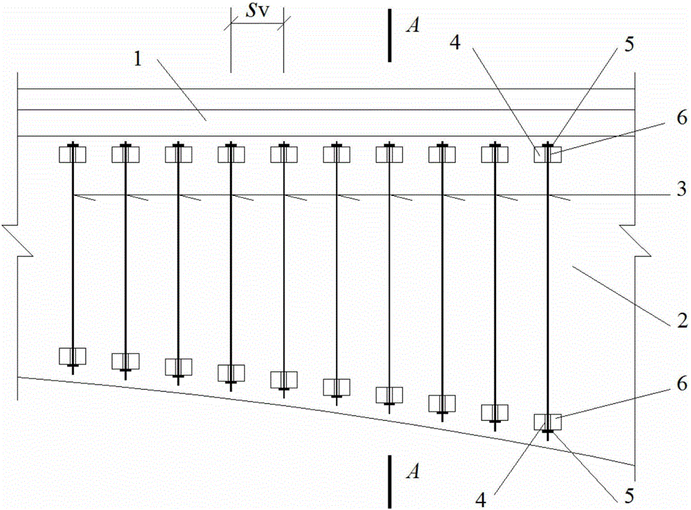
The invention discloses a reinforcement structure for inclined cracks in a main girder web plate of a box girder bridge. Anchor blocks, corresponding up and down and being arranged in an axial direction of a bridge at intervals, are additionally arranged on two outer side faces of the main girder web plate at a section having the inclined cracks, wherein vertical externally prestressed reinforcing bars made of finish-rolled threaded reinforcing bars are mounted on the anchor blocks; during construction, the vertical externally prestressed reinforcing bars are tensioned in a way of screwing nuts at the lower ends of the vertical externally prestressed reinforcing bars; meanwhile, an angular frequency of first-order vibration when the vertical externally prestressed reinforcing bars are tensioned is detected by a vibration pickup device mounted on the vertical externally prestressed reinforcing bars; a tensile force generated by the vertical externally prestressed reinforcing bars is calculated according to a formula; when the tensile force reaches a theoretical tensile force generated in the vertical externally prestressed reinforcing bars, the tensioning is stopped. The reinforcement structure plays a reinforcement role on the main girder web plate by forming a vertical compressed stress on the main girder web plate through the vertical externally prestressed reinforcing bars, while ensuring that an original structure of the bridge is not damaged due to excessive tensile force.

Description

technical field [0001] The invention relates to highway bridges, in particular to a reinforcing structure for oblique cracks in the main girder web plate of a box girder bridge and a construction method thereof. Background technique [0002] The box girder bridges include ordinary concrete box girder bridges and prestressed concrete box girder bridges, which are divided into ordinary reinforced concrete continuous girder bridges, prestressed concrete continuous girder bridges and prestressed concrete continuous rigid frame bridges according to the main structural forms. . Among them, the box girder bridge with a span of 20m to 300m is the most commonly used type. Due to problems in design, construction or operation management, a considerable proportion of such concrete box girder bridges currently in service have problems such as oblique cracks in the main girder web caused by excessive main tensile stress, and the cracks are relatively large. When it is large, it directly...

Claims


Application Information

Patent Timeline
Patent Type & Authority Applications(China)
IPC IPC(8): E01D22/00E01D2/04
CPCE01D2/04E01D22/00
Inventor 庞兴薛兴伟张海
Owner 广州展亚土木工程技术有限公司
Learn More