
Mold Apparatus And Resin Molding Method

A technology of resin molding and moulding, which is applied to household appliances, other household appliances, household components, etc., can solve problems such as the movement of the rotating core, and achieve the effect of preventing the occurrence of the core wire

Active Publication Date: 2016-07-06
HONDA MOTOR CO LTD
View PDF3 Cites 3 Cited by
  • Summary
  • Abstract
  • Description
  • Claims
  • Application Information

AI Technical Summary

Problems solved by technology

However, in this method, the rotating core tends to move toward the mold unit due to the pressure of the resin, and a step difference occurs between the rotating core and the mold body during molding, causing unwanted core wires to form in the molded product.

Method used


Image

  • Mold Apparatus And Resin Molding Method
  • Mold Apparatus And Resin Molding Method
  • Mold Apparatus And Resin Molding Method

Examples


Embodiment Construction

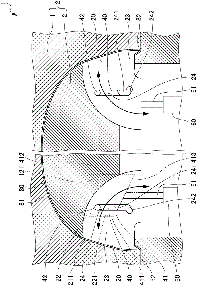
[0042] Below, while referring to the attached Figure 1 A preferred embodiment of the mold device of the present invention will be described. figure 1 It is a figure which schematically shows the mold apparatus 1 which concerns on one Embodiment of this invention.

[0043] As one embodiment of the present invention, a mold device 1 for resin-molding a bumper of an automobile as a molding 80 will be described. Such as figure 1 As shown, the molding 80 is comprised of a body portion 81 and a barb portion 82 formed at the end of the body portion 81 . The barb portion 82 of the molding 80 constitutes a portion for mounting the bumper portion to a vehicle body made of metal. The barb portion 82 of the present embodiment has a V-shaped cross-sectional shape.

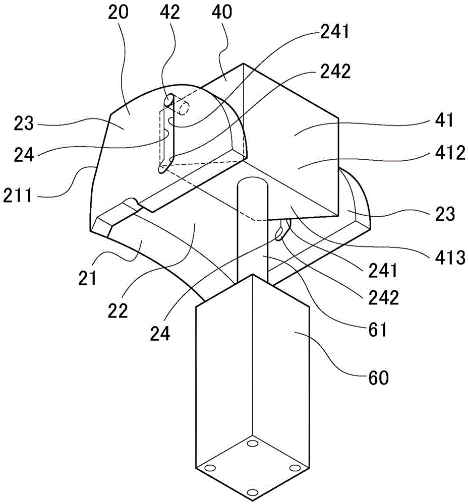
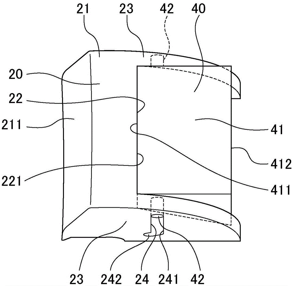
[0044] Each structure of the mold device 1 for molding the molded product 80 will be described. The mold device 1 of the present embodiment includes a mold body 2 , a rotary core 20 , a restricting core 40 , and a drive c...


PUM


Abstract

The mold apparatus (1) includes: the stationary mold (12) of the mold main body (2) that molds the main body part (81); the rotary core (20) that molds the undercut part (82) and mold releases by rotationally moving in a direction separating from the undercut part (82); and the restricting core (40) that restricts movement of the rotary core (20) sandwiching between the stationary mold (12) and rotary core (20) during molding, and releases restriction of the rotary core (20) by moving in a direction exiting from between the stationary mold (12) and rotary core (20) during mold release of the rotary core (20) from the undercut part (82).

Description

technical field [0001] The present invention relates to a mold device for resin-molding a molded article having a barb portion. Background technique [0002] Conventionally, there is known a technique for releasing a core that molds a barb portion from the barb portion by rotational movement in a mold apparatus for resin-molding a molded article having a barb portion. Patent Document 1 exists, for example, as a technique disclosing such a core that is released from a barb portion by rotational movement. Patent Document 1 discloses a technique in which a rotating core is formed such that a sliding contact surface with a mold body is a curved surface, and the rotating core is released from a barb portion by being rotated along the sliding contact surface. [0003] prior art literature [0004] Patent Document 1: Japanese Patent Application Laid-Open No. 6-114893 [0005] However, in a mold device that performs resin molding, resin pressure is applied to the surface forming ...

Claims


Application Information

Patent Timeline
Patent Type & Authority Applications(China)
IPC IPC(8): B29C45/40B29C45/33
CPCB29C45/332B29C45/40B29C45/2681B29C45/4471B29L2031/3044
Inventor 内智幸松岛央阿部贵士
Owner HONDA MOTOR CO LTD
Learn More